
While visible light image sensors may be the baseline “one sensor to rule them all” included in all autonomous system designs, they’re not necessarily a sole panacea. By combining them with other sensor technologies:
-
“Situational awareness” sensors; standard and high-resolution radar, LiDAR, infrared and UV, ultrasound and sonar, etc., and
-
“Positional awareness” sensors such as GPS (global positioning system) receivers and IMUs (inertial measurement units)
the resultant “sensor fusion” configuration can deliver a more robust implementation in applications such as semi- and fully-autonomous vehicles, industrial robots, drones, and other autonomous devices. This article discusses implementation options, along with respective strengths and shortcomings of those options, involved in combining multiple of these sensor technologies within an autonomous device design.
Most sensors are single-purpose: one type of sensor for temperature, another for magnetic field, another for ambient light, etc. Image sensors are unique in that, when coupled with the right algorithms and sufficient processing power, they can become “software-defined sensors,” capable of measuring many different types of things.
For example, using video of a person’s face and shoulders, it’s possible to identify the person, estimate their emotional state, determine heart rate and respiration rate, detect intoxication and drowsiness, and determine where the person’s gaze is directed. Similarly, in cars and trucks, a single image sensor (or a small cluster of them) can detect and identify other vehicles, brake lights, pedestrians, cyclists, lane markings, speed limit signs, roadway and environment conditions, and more.
However, as their name implies, the performance of visible light image sensors, the most common category in widespread use today, can be sub-optimal in dimly lit settings, as well as at night; rain, snow, fog and other challenging environments can also notably degrade their discernment capabilities. And the ability to ascertain the device’s current location and orientation, along with route direction, rate and acceleration, is also indirect at best, derived by recognizing landmarks in the surroundings and approximating the device’s relative position to them.
Infrared and ultraviolet image sensors have range, resolution and other shortcomings but can also provide useful spectral information absent from a visible-light-only perspective of a scene. Radar, sonar and ultrasound work well after dark, although while they’re good at detecting physical objects, they can’t readily identify those objects, nor can they discern visible messages such as street signs, road markings, brake lights, or the color of traffic lights. LiDAR improves on radar from a resolution standpoint, albeit with notable size, weight, power consumption, cost and other tradeoffs. And the GPS and IMU modules now pervasive in smartphones and the like can also find use in determining an autonomous device’s location, orientation, speed, acceleration, and other positional characteristics.
This article discusses implementation options, along with respective strengths and shortcomings of those options, involved in combining multiple of these sensor technologies within an autonomous device design, in order to provide the autonomous device both with redundancy and with enhanced insight into its surroundings as well as its relationship with those surroundings. Both traditional and deep learning-based algorithms are highlighted, along with both general concept recommendations and detailed specific explanations, the latter in the form of case study examples. And this article also introduces readers to an industry alliance created to help product creators incorporate vision-enabled capabilities into their SoCs, systems and software applications, along with outlining the technical resources that this alliance provides (see sidebar “Additional Developer Assistance“).
Sensor Fusion-based System Modeling and Software Development
Developing a sensor fusion-based design from a hardware standpoint is only one part of the full implementation process. Software running one or multiple heterogeneous processors also needs to be developed in order to make sense of, and react appropriately to, the multiple streams of data sourced by the various sensors in the design. The following section, authored by MathWorks, explores this topic in depth.
The development of increasingly autonomous systems is experiencing exponential growth. Such systems range from roadway vehicles that meet various NHTSA (National Highway Traffic Safety Administration) levels of autonomy, through consumer quadcopters capable both of autonomous flight and remote piloting, package delivery drones, flying taxis, robots for disaster relief and space exploration, and the like. Work underway focusing on autonomous systems spans diverse industries and includes both academia and government.
In broad terms, the processing steps of every autonomous system include sensing, perception, decision-making, and action execution, i.e., control functions. Figure 1 illustrates how these functions interrelate.
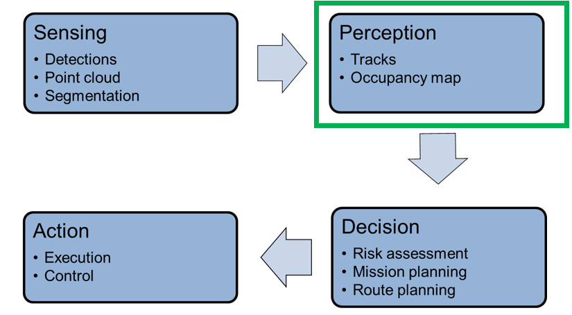
Figure 1. Autonomous systems’ processing steps involve the interrelationship of various functions (courtesy MathWorks).
Autonomous systems rely on sensor suites that provide data about the surrounding environment to feed the perception system. These suites include radar and vision cameras, which provide detections of objects in their field of view, LiDAR, which provide point clouds of returns from obstacles in the environment, and (in some cases) ultrasound and sonar sensors. Signal processing that occurs in the sensor system includes detection, segmentation, labeling, and classification, often along with basic tracking to reduce false alarms.
MathWorks has identified and is addressing an immediate and growing need for a toolset dedicated to sensor fusion and tracking that is reusable, shareable, flexible and configurable. Sensor fusion and tracking are at the heart of the perception block in Figure 1. By providing these tools, much of the effort that is currently spent on “reinventing the wheel” with every new autonomous system development project can be greatly reduced, if not eliminated. MathWorks’ goal is to enable researchers, engineers, and enthusiasts to develop their own autonomous systems with significantly reduced time, effort, and funding. In addition, the tools we’re developing also enable sharing of best practices and best results, both within an organization and across organizations and disciplines.
The toolset integrates sensor fusion and tracking algorithms into complete trackers, and also provides a comprehensive environment that allows for simulating sensor data, swapping trackers, testing various sensor fusion architectures, and evaluating the overall tracking results as compared to the simulated truth. These tools help researchers and developers that want to select the optimal perception solution to meet the requirements and sensor suites of their autonomous systems.
Figure 2 shows the toolset architecture. MATLAB and Simulink provide a framework to explore centralized and decentralized sensor fusion architectures. This framework also supports various models that extend to two- and three-dimensional environments.
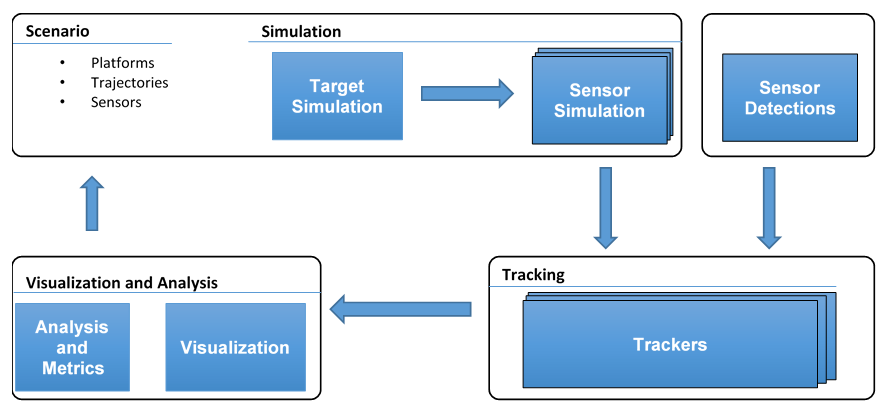
Figure 2. A toolset architecture for sensor fusion system modeling and software development supports both centralized and decentralized architectures (courtesy MathWorks).
Sensor fusion is also required to perform localization. The fusion of GPS and inertial sensors enable self-awareness for an autonomous system. For navigation and tracking, the self-awareness information must be tightly coupled with the perception algorithms. Specifically, localization is used to determine pose, orientation, and position. This coupling is enabled with sensor models and fusion algorithms for IMU and GPS positions as shown in the workflow in Figure 3. Positional information is required by multi-object trackers because the autonomous system needs to know where it is at all times in order to keep track of objects in its occupancy grid.
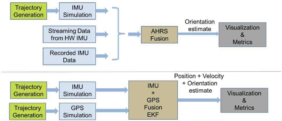
Figure 3. Self-awareness for autonomous systems requires tight coupling of various sensors and their associated algorithms (courtesy MathWorks).
In the case of GPS-denied environments such as an urban “canyon”, the inertial measurements from an IMU can alternatively be fused with visual odometry in order to provide improved positional accuracy.
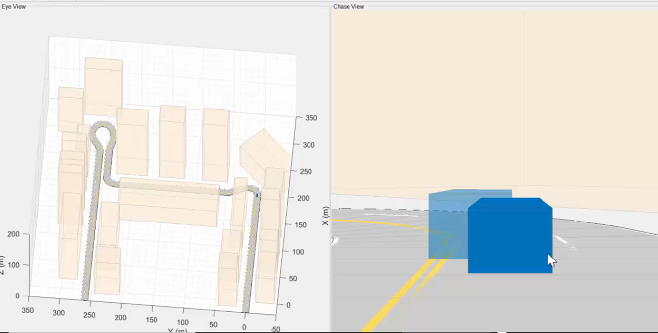
Figure 4. Visual odometry is a feasible sensor fusion alternative in environments where GPS capabilities are compromised (courtesy MathWorks).
Scenario definition tools can find use in defining the “ground truth” (the environmental information provided by direct observation i.e., empirical evidence, as opposed to being inferred by implication). Platforms, which are simulated representations of ground truth objects, can be represented as either point targets or extended objects. Their positions in space over time, including their poses and orientations, are defined by attaching a trajectory to the target. Each platform can be assigned multiple signatures. Each signature defines how that object interacts with the sensor simulation.
Simulated sensors can also be assigned to the platform, allowing them to sense other platforms in the environment. Because sensors in autonomous systems can have very high resolution, system models must account for extended objects with multiple detections. Figure 5 shows how it’s possible to track these detections as a group, versus clustering them to only individual detections.
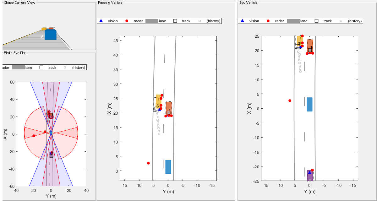
Figure 5. System models must comprehend sensors with very high resolutions (courtesy MathWorks).
With scene generation, it’s possible to focus on corner cases that may be difficult to capture with recorded data. Complex scenes can be set up, and detections can be synthesized directly, to test algorithms and configurations prior to live testing.
It’s also important to maintain an open interface with the trackers. In such a way, detections obtained from actual sensors can be provided to a range of trackers with a common API, which captures the necessary information passed to the tracker: time of detection, measurement, uncertainty, classification, and information about the sensor that made the detection and its coordinate system.
Finally, we realize that we can’t envision the needs of all users. MathWorks makes tracker components that are building blocks, which developers can reuse in constructing their own trackers. Some examples of these building blocks include track confirmation and deletion logic based on history and score, and track management.
After a system is modeled, C code can then be generated from the system’s algorithms. This C code can be used to accelerate simulation times, to integrate into a larger simulation framework, or to deploy to a general-purpose processor and/or one or multiple specialized processors.
Avinash Nehemiah
Product Manager, Deep Learning, Computer Vision and Automated Driving
MathWorks
Case Study: Autonomous Vehicles
ADAS (advanced driver assistance systems)-equipped and fully self-driving vehicles aren’t the only autonomous devices on the market and under development, but they may be the most famous examples of the product category. In the following section, Synopsys describes the opportunity for sensor fusion in this particular application, along with implementation details.
ADAS use multiple technologies to obtain the context of the external environment and implement object detection. Radar, LiDAR, imaging and ultrasonic sensors around the car each offer different capabilities in terms of distance, resolution and other characteristics, and together enable robust 360-degree capture. Figure 6 shows the different sensor technologies and their uses in an autonomous car design. Imaging technologies, for example, offer the ability to view images at short and medium distances and can be used for surround view and parking assist, as well as traffic signal and sign detection.
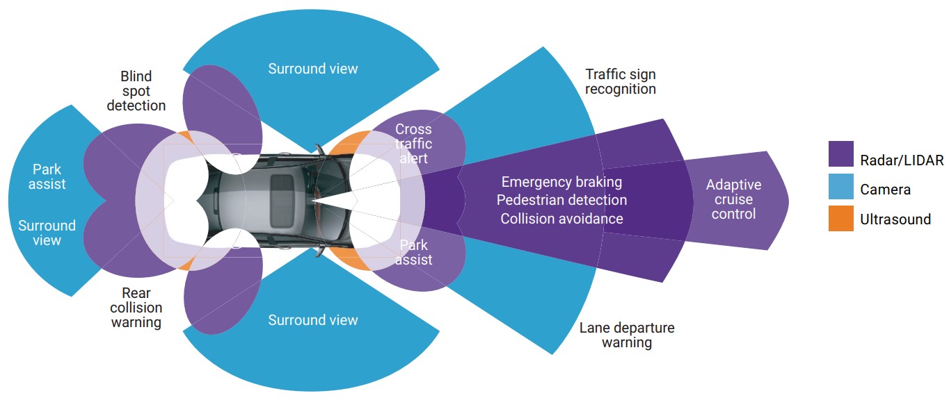
Figure 6. Numerous sensor technologies with varying capabilities can find use in autonomous vehicle designs (courtesy Synopsys).
Traditional automotive systems implement distinct sensor and computation paths up to the point where objects are detected. Cloud points or processed images are then created and passed to a sensor-fusion processing core, where other locational information is also applied. Figure 7 shows a traditional system design; from multiple technology sensors through signal processing, detected points, sensor fusion and then the applications processor.

Figure 7. A traditional system design implements distinct computation paths, up to a point, for each sensor technology employed (courtesy Synopsys).
In sub-optimal everyday-use conditions, such as in poor weather or at night, imaging may be less able to provide useful, reliable data points for object detection and tracking than in situations with more amenable environmental characteristics. LiDAR is alternatively well suited to night conditions but is negatively impacted by poor weather. Radar is robust across varying environmental conditions, but is less precise than other sensor technologies with respect to object definition.
Front-focused sensors’ critical functions involve the detection of objects such as pedestrians and other vehicles. Such objects can rapidly change directions and path, thereby leading to the need for an autonomous vehicle to quickly apply path correction and collision avoidance techniques. Front-focused sensor arrays often employ radar for object detection, and can also use LiDAR for full environment mapping. Compounding weather and environmental conditions require data from imaging, radar and LiDAR systems to cross-reference and efficiently identify object data. The fusion and cross computation of data between these various systems provides the highest reliability view of the surrounding environment.
The trend toward cross-computation is evolving the optimal location of computation fusion within the system. Radar and LiDAR processing and perception stages, for example, can be fused into a single processing unit that provides both the LiDAR cloud point data and the radar-detected object point. Cross-referencing and cross-computing these various data points will result in more accurate, higher reliability object detection and identification. In addition to radar- and LiDAR-specific algorithms’ computation, the cross-computation support provides for sensor fusion capabilities. Such algorithms tend to focus heavily on linear algebra from a mathematical computation standpoint.
Case Study: Industrial Automation
Robots are finding increasing adoption in environments ranging from consumer to military systems, along with numerous interim application points. One of the most common usage scenarios today is in the manufacturing world, from initial piece parts acquisition through assembly line production and all the way through to finished goods warehouse inventory management. Synopsys shares its perspectives on the industrial automation opportunity for sensor fusion, in the following section.
In addition to the earlier mentioned automotive applications, industrial automation applications can also benefit from the fusion of radar, LiDAR and imaging. With the emerging wave of industrial Internet of Things implementations, individual industrial machines can operate autonomously as well as communicate with each other and their human monitors. These industrial robotic vehicles operate in a more controlled environment than do automotive systems, and are likely to perform more repetitive and limited motions. With that said, the robot still requires visibility of its surroundings as well as of other robots and human workers. The safety constraints and considerations are still evolving and depend upon the use and range of the mobile robot devices.
Industrial automation environmental conditions are also simpler and more controlled than those in automotive in illumination and visibility; after all, it usually does not rain, snow or get foggy or pitch black in factory buildings! The image sensors, often combined with LiDAR, can therefore be of lower resolution and cost. As in automotive applications, the combination of image and LiDAR processing provides for a superior representation of the environment as well as detection of objects. Robotic vehicles are often battery-powered, so reducing the total sensor count and combined power consumption are critical objectives.
The ability to fuse the computation and processing of all sensor data, as well as other sensor fusion inputs such as Wi-Fi-determined location, into one single processing unit provides for a very low-cost and low-power solution for industrial automation. Such a capability also provides the ability to offer a common foundation product capable of implementing a range of small to large autonomous driving robots in the industrial automation space (Figure 8).
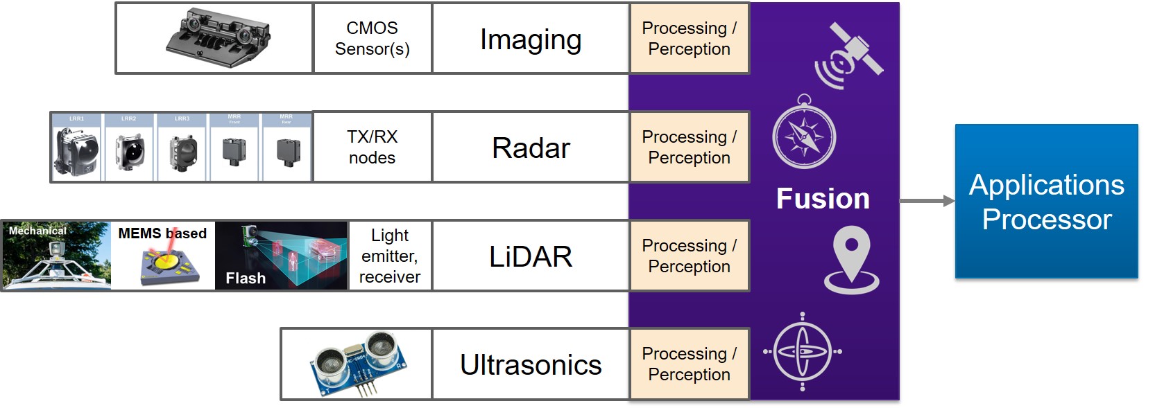
Figure 8. The ability to merge the computation of all sensor data within a single processing unit allows for straightforward design of a scalable range of autonomous products (courtesy Synopsys).
One possible ISA (instruction set architecture) that covers all of these computation requirements is a unified-core VLIW (very long instruction word) architecture for high parallel operation execution, with wide SIMD (single instruction, multiple data) computation of vector data. Such a scheme provides the fundamental architecture needed to operate on data at the required performance throughput. The ISA and data type support, as well as register banks and load/store definitions, need to be more complex than with legacy DSP cores, as support for integer, fixed point and complex data types is necessary (Table 1). Floating-point computation capabilities are also critical for preserving accuracy and dynamic range.
| LiDAR / Imaging | Linear Algebra | Radar | |
| Algorithms / computation | Image computation | Kalman filters, Cholesky, Vector operations, mathematical algebra | Complex FFT filters, Clustering, Filtering. Kalman filters |
| Architecture | Wide SIMD and VLIW | Wide SIMD and VLIW | Wide SIMD and VLIW |
| Data Types | Integer (8b), Fixed Point (16b). Possible Floating Point (half and single precision) | Complex (16b + 16b). Floating Point (half and single precision) | Fixed Point (16b). Complex (16b + 16b). Possible Floating Point (single precision) |
| Compiler | C-Compiler and OpenCL Compiler | C-Compiler | C-Compiler |
Table 1. Algorithm, data type, programming language and other requirements of various sensor fusion subsystems (courtesy Synopsys).
One of the major differences between the various usages of the common single processing core involves the programming and compiler support. Imaging algorithms have traditionally been programmed in OpenCL. Fixed-point algorithms used in radar, LiDAR and controller algorithms, however, are commonly programmed in C, hence necessitating a C compiler. A combined processor/DSP core therefore needs to offer a unified programming model across both OpenCL and C. The unified compiler has to be able to support the syntax of both programming languages, as well as to efficiently map these different syntaxes to the common architecture and ISA of the processor.
Graham Wilson
Senior Product Marketing Manager, ARC Processors
Synopsys
Case Study: Drones
Drones (i.e., quadrotors) are a popular and increasingly widespread product used by consumers as well as in a diversity of industrial, military and other applications. Historically fully under the control of human operators on the ground, they’re becoming increasingly autonomous as the cameras built into them find use not only for capturing footage of the world around them but also in understanding and responding to their surroundings. The following section from FRAMOS explains how combining imaging with other sensing modalities can further bolster the robustness of this autonomy.
When a drone flies, it needs to know where it is in three-dimensional space at all times, across all six degrees of freedom for translation and rotation. Such pose estimation is crucial for flying without crashes or other errors. Drone developers are heavily challenged when attempting to use a single IMU or vision sensor to measure both orientation and translation in space. A hybrid approach combining IMU and vision data, conversely, improves the precision of pose estimation for drones based on the paired strengths of both measuring methods.
The IMU sensor measures acceleration, with information about the orientation derived from its raw output data. In theory, such acceleration measurements could also be used to derive translation. However, to calculate such results, developers need to integrate twice, a process that results in increased errors. Therefore, the IMU sensor alone is not an accurate source of precise location information.
In contrast, the vision sensor is quite good at measuring location; it’s sub-optimal at determining orientation, however. Particularly with wide-view angles and long-distance observation, it’s quite complicated for the vision system alone to measure orientation with adequate precision. A hybrid system of paired IMU and vision data can provide a more precise measurement for the full six degrees of pose in space, providing better results than using either the IMU or the vision sensor individually.
The most challenging issues in such a sensor fusion configuration are to determine a common coordinate frame of reference for both orientation and translation data, as well as to minimize the noise produced by the sensors. A common approach to create the reference frame leverages linear Kalman filters, which have the capability to merge both IMU and vision data for hybrid pose estimation purposes. For a vision system mounted on or embedded in the drone, SLAM (simultaneous localization and mapping) provides spatial awareness for the drone by mapping their environment to ensure that it does not collide with trees, buildings, other drones or other objects.
Factors to Consider When Building a Hybrid Sensor-based Drone System
Several key factors influence the measurement quality. First off, the quality results of an IMU’s measurements highly depend on the quality of the IMU selected for the design. Inexpensive IMU tend to generate high noise levels, which can lead to various errors and other deviations. More generally, proper calibration is necessary to comprehend the filter’s characteristics, e.g. the sensor’s noise model. Individual sensors, even from the same model and manufacturer, will have slightly different noise patterns that require consideration.
On the vision side, the implementation specifics fundamentally depend on whether a global or rolling shutter image sensor is being used. With a global shutter image sensor, every pixel is illuminated at the same time, with no consequent read-out distortion caused by object motion. With a more economical rolling shutter image sensor, conversely, distortion can occur due to read-out time differences between pixels. IMU information can correct for rolling shutter artifacts, historically by the use of various filter methods. Nowadays, the noise reduction of the IMU sensor can also be corrected by deep learning-based processing.
Combining IMU and Vision Data
One challenge with hybrid systems is that the captured vision data is often very slow from a frame rate standpoint, usually well below 100 Hz, while the IMU data comes across at high frequency, sometimes well over 1 KHz. The root of the resultant implementation problem lies in finding a way to obtain information from both systems at the exact same time. SLAM techniques such as Continuous Trajectory Estimation can approximate the drone’s movement by assuming that the drone’s speed is continuous.
Developers can integrate both the IMU and vision data into an environment with a common reference frame, allowing them to assign measurements to a specific part of the continuous trajectory. In-between any two image acquisitions, multiple IMU measurements provide additional reference points regarding this trajectory. When in the air, the drone will then constantly be time-synchronized and updated with IMU data. And every time a vision image is received, it then corrects the IMU information.
Hardware Requirements, Implementation and Testing
Considering the drones’ limited integration space and more general resource-limited embedded nature, implementing a robust setup for synchronization of the IMU and vision data is not straightforward. Light and lean components with powerful processing units are necessary, in a limited memory footprint while consuming little power. Stabilized sensors and software filtering are also essential for SoC developers as a result of the extreme jitter due to propeller movement, which influences the vision components of the design.
Both the vision sensor and IMU have individual local reference systems to measure their own pose, which need to be calibrated to ensure a hybrid SLAM has a common reference frame. Each system must be calibrated individually first, and then co-calibrated with respect to each other, in order to receive the position in the common reference frame. Multiple data sets are available to test aerial vehicle pose estimation, also in hybrid fashion, with the developed pipelines. The most commonly used dataset is EuRoC, which provides raw vision and IMU data to test algorithms and compare against other methods.
Ute Häußler
Corporate Editor, Content and PR
FRAMOS
Conclusion
While visible light image sensors are often included in autonomous system designs, they’re not necessarily the sole required sensor technology in all implementation situations. By combining them with other sensors, however, the resultant “fusion” configuration can deliver a robust implementation in applications such as semi- and fully-autonomous vehicles, industrial robots, drones, and other autonomous devices.
Additional Developer Assistance
The Embedded Vision Alliance® is a global partnership that brings together technology providers with end product and systems developers who are enabling innovative, practical applications of computer vision and visual AI. FRAMOS, MathWorks and Synopsys, the co-authors of this article, are members of the Embedded Vision Alliance. The Embedded Vision Alliance’s mission is to provide product creators with practical education, information and insights to help them incorporate vision capabilities into new and existing products. To execute this mission, the Embedded Vision Alliance maintains a website providing tutorial articles, videos, code downloads and a discussion forum staffed by technology experts. Registered website users can also receive the Embedded Vision Alliance’s twice-monthly email newsletter, Embedded Vision Insights, among other benefits.
The Embedded Vision Alliance’s annual conference and trade show, the Embedded Vision Summit®, is coming up May 20-23, 2019 in Santa Clara, California. Intended for product creators interested in incorporating visual intelligence into electronic systems and software, the Embedded Vision Summit provides how-to presentations, inspiring keynote talks, demonstrations, and opportunities to interact with technical experts from Embedded Vision Alliance member companies. The Embedded Vision Summit is intended to inspire attendees’ imaginations about the potential applications for practical computer vision technology through exciting presentations and demonstrations, to offer practical know-how for attendees to help them incorporate vision capabilities into their hardware and software products, and to provide opportunities for attendees to meet and talk with leading vision technology companies and learn about their offerings. More information, along with online registration, is now available.
The Embedded Vision Alliance also offers a free online training facility for vision-based product creators: the Embedded Vision Academy. This area of the Embedded Vision Alliance website provides in-depth technical training and other resources to help product creators integrate visual intelligence into next-generation software and systems. Course material in the Embedded Vision Academy spans a wide range of vision-related subjects, from basic vision algorithms to image pre-processing, image sensor interfaces, and software development techniques and tools such as OpenCL, OpenVX and OpenCV, along with Caffe, TensorFlow and other machine learning frameworks. Access is free to all through a simple registration process. The Embedded Vision Alliance and its member companies also periodically deliver webinars on a variety of technical topics, including various machine learning subjects. Access to on-demand archive webinars, along with information about upcoming live webinars, is available on the Alliance website.