Vision technologies are rapidly emerging in the automotive market and improving the safety of vehicles. Fused with other technologies such as RADAR, LIDAR, and far infrared sensors, the automobile is well on its way to becoming fully self-driving.
By Michael McDonald
President, Skylane Technology Consulting
Consultant, Embedded Vision Alliance
Many of us have been affected, directly or indirectly, by a car accident at some point in our lives. A World Health Organization (WHO) report “Global Status Report on Road Safety 2013”, estimates there are world-wide about 1.2 million vehicle-related fatalities and over twenty million reported injuries a year; including unreported accidents, the true number of injuries is estimated to be double this amount. In Europe, car accidents are the leading cause of death for young people 5-29 years of age. World-wide, car accidents cost societies an estimated $2 trillion per year, or as much as 3% of the global world economy.
Car manufacturers are aggressively working to reduce the accident rate through the advancement of “advanced driver assistance systems,” more commonly known as ADAS. These same systems enable vehicles to become increasingly self-driving in the future, freeing people from mundane driving tasks like sitting in rush-hour traffic or searching for parking. Long-term, self-driving cars have the ability to revolutionize car ownership models through car sharing. Taxi services and shipping and delivery services may also undergo significant change with self-driving vehicles. Some experts have argued that self-driving cars could have unexpected benefits on items like US health care, since many of the 33,000 annual fatalities and 2.5 million ER visits related to automobile accidents would be eliminated.
The tremendous variability of the real world coupled with the substantial consequences of sensing and processing failure are currently the limiting factors in a “silver bullet” one-size-fits-all solution to ADAS. The good news, however, is that by combining mature sensing technologies like RADAR with emerging technologies like vision and LIDAR, a comprehensive virtual picture of the environment and situation is captured by the system, increasing the safety and reliability of these safety systems.
RADAR
In 1904, an early implementation of RADAR technology detected the presence of ships in fog. Today, RADAR is still highly valued because it provides distance and velocity information that is largely immune to challenging environmental conditions like fog, rain, wind, darkness, or blinding sun. An active method of detection, RADAR uses a transmitter that radiates radio waves and a receiver that collects the waves reflected off of an object. By detecting slight changes in the reflected wavelengths, RADAR uses the Doppler Effect to accurately detect the velocity of objects. The ability of RADAR to detect an object is largely dictated by the strength of the reflection which is influenced by factors such as the object’s size, its distance and absorption characteristics, the reflection angle, and the strength of the original transmission.
Many scenarios are challenging for RADAR, however (Figure 1). Driving involves interacting with pedestrians and motorcycles, which are small relative to a vehicle or truck. In addition, pedestrians and motorcycles have few hard or metallic shapes that reflect RADAR signals. If a motorcycle is next to a large truck, the reflection of the truck can hide the reflection of the motorcycle. If a small child is standing next to a vehicle or a person is standing between two parked cars, the large vehicle reflections can similarly obscure the reflection of the human. Two objects next to each other on the road can provide very similar reflections, making the respective reflections – and corresponding objects – difficult to distinguish.
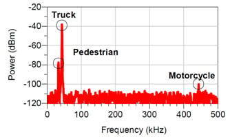
Figure 1. An example RADAR return for a truck and pedestrian located roughly 15 m away, and a motorcycle 150 m away. Note how the pedestrian reflection is almost hidden by the truck, and the difficulty of identifying anything more than the presence and distance of an object via the RADAR signals (Credit: Camilla Kärnfelt, “77 GHz ACC Radar Simulation Platform”, ITST 2009)
Automotive RADAR systems are small, static systems designed to seamlessly blend with the vehicles exterior; this limits the transmitter and receiver sizes which forces tradeoffs in range, field of view, and angular resolution. As a result, angular resolution is also very limited, which means that it is difficult to resolve small details of objects which could aid in object identification. While it is helpful to detect the presence and distance of an obstacle, qualitative information is not provided by RADAR, such as whether the object is a pole or a person.
RADAR also trades off range versus field of view (Figure 2). To identify objects at longer distances (a requirement for higher-speed highway traffic), long-range radar systems capable of distances exceeding 250 meters have a beam width of about 15 degrees. This narrow beam effectively only allows measurements of objects directly in front of the car, missing vehicles or other objects nearby in adjacent lanes. Mechanical and multi-beam solutions increase these systems' field of view, but they require larger sensor sizes, and higher compute complexity and system complexity, resulting in systems with higher cost, greater power consumption, and larger size and weight.
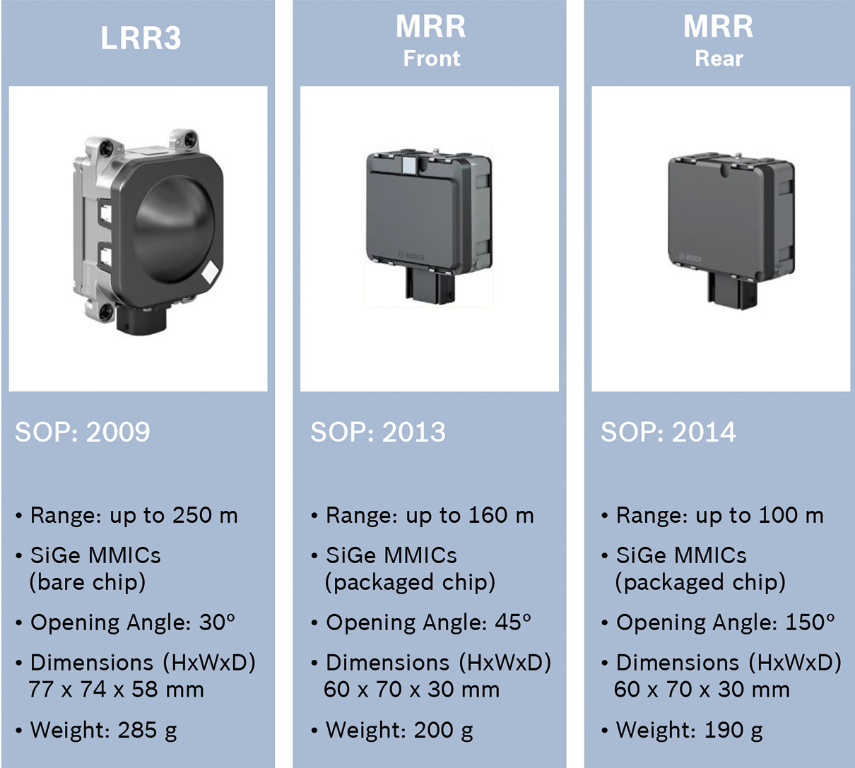
Figure 2. Example medium- and long-range automotive radar sensors operating up to 250 meters. Note the tradeoff in field of view ("opening angle") and effective range (Source: Bosch)
Vision
While RADAR is good at detecting physical objects, it cannot readily identify objects, nor can it detect visible messages such as street signs, road markings, brake lights, or the color of traffic lights. Computer vision techniques address these needs by extracting information from visual images and converting that information into a warning or response by the vehicle.
While computer vision systems are challenged by many of the same environmental and situational factors that make it difficult for people to see (see sidebar "Environmental Challenges"), increasingly capable sensors, processors and software are making vision-based ADAS implementations more robust and practical.
A rapidly increasing number of car models are incorporating forward-facing vision solutions that enable safety features such as lane-keeping assist (LKA), automatic cruise control (ACC), and automatic emergency braking (AEB). Cameras on the side of the car offer blind spot monitoring and parking assistance. One of the more serious challenges drivers face is seeing into a potentially dangerous intersection; cameras placed at the front and rear corners of the vehicle can assist in this regard, for example by preventing the car from moving if it identifies a hazard. In addition, side-facing cameras will also soon assist, and eventually automate, vehicle passing maneuvers.
Vision solutions are also appearing within the vehicle (Figure 3). For example, to potentially reduce lane departure warning (LDW) false alarms that might arise from a person changing lanes without using a turn signal, vision processing can identify whether a person has looked at a side mirror prior to changing lanes. By looking at a person’s face, that same vision system can also detect whether a person is drowsy or, by using facial recognition, who is driving the car and adjust systems – audio, seat position, HVAC, mirrors, or even whether the car will start. Using such a system, for example, a parent could configure the car to drive more conservatively when operated by a teenager.
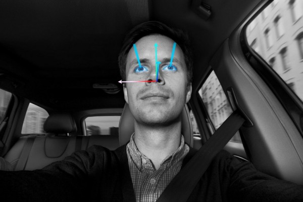
Figure 3. Face detection systems inside the vehicle can detect driver fatigue and discern where his or her attention is directed (Credit: Volvo)
Also contributing to safety, vision solutions can determine the size and orientation of vehicle occupants – are feet propped on the dash, for example, or is there a child seat present? – and adjust the airbags for optimal deployment. A different vision solution directed at a person’s foot can prime the brakes for faster braking or to drive more cautiously if a person’s foot is hovering over the brake.
An important factor in the growing use of vision in ADAS is the fact that it uses cost-effective, high-volume semiconductor technologies. Vision sensors and processors are built using CMOS semiconductor processes, the same manufacturing process used for most consumer electronics products. This enables them to leverage economies of scale, rapid innovation, and the potential for high single-chip integration. This situation differs from that of RADAR, which is moving to high frequencies – around 77 GHz – and requires high output power, wide dynamic range, and extended linearity in order to detect vehicles and other objects at longer distances. CMOS processes are currently unable to achieve all of these requirements, so RADAR components use high-speed specialized SiGe (silicon germanium) fabrication processes, with a separate CMOS device employed for lower-speed signal processing. This multi-chip approach limits RADAR's integration potential, increasing system size and cost.
With the growing deployment of vision-based ADAS, a multi-billion dollar opportunity is quickly evolving and many players are emerging. MobilEye, VisLab, ADASENS, Aisin Seiki, HARMAN (which acquired iOnRoad last year), AutoLiv, ImageNEXT, Valeo, Delphi, and Bosch are among the companies that are developing vision-based ADAS systems companies. Many of these companies provide complete camera hardware systems that leverage vision algorithms developed by MobilEye. The quality and performance of these algorithms is closely correlated to the size and breadth of the database. Companies like MobilEye, which recently held a successful IPO and now has a valuation approaching $10 billion, have powerful algorithms based on extensive databases covering a wide variety of driving conditions.
LIDAR
LIDAR is an active sensing solution that determines distance by emitting infrared laser light and measuring the amount of time it takes for the light to reflect and return to the source. Measuring this round trip time provides a very accurate measure of the distance to an object.
The LIDAR system emits a narrow laser beam, and only collects information along that narrow path; for car manufacturers using LIDAR as a replacement to RADAR, the narrow field of view coming from a single forward-facing laser is sufficient. Various cars already have single laser LIDAR solutions like this.
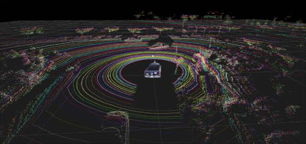
However, to achieve a 360-degree horizontal field-of-view depth map around a car, current LIDAR systems such as that from Velodyne use a mechanical, rotating system that rotates the laser in all directions. In addition to wear and tear in such a mechanical system, it is also neither aesthetically pleasing nor aerodynamic. These 360-degree LIDAR systems are also quite expensive, with prototype systems today costing upwards of $70,000.
Vertical resolution is also a challenge. Velodyne’s LIDAR sensor, used in many self-driving cars including Google’s test vehicles, has a vertical resolution of 64 pixels. In order to achieve adequate vertical pixel density, the vertical field of view is limited to about 26 degrees, preventing the system from detecting objects directly in front of a vehicle, such as a curb or pothole (Figure 4). Compounding the problem, newer 360-degree systems reduce the vertical resolution to 16 or 32 pixels in order to shrink the sensor's size (Figure 5). For systems with a single laser, no vertical resolution exists; the system is only able to identify the distance to an object.
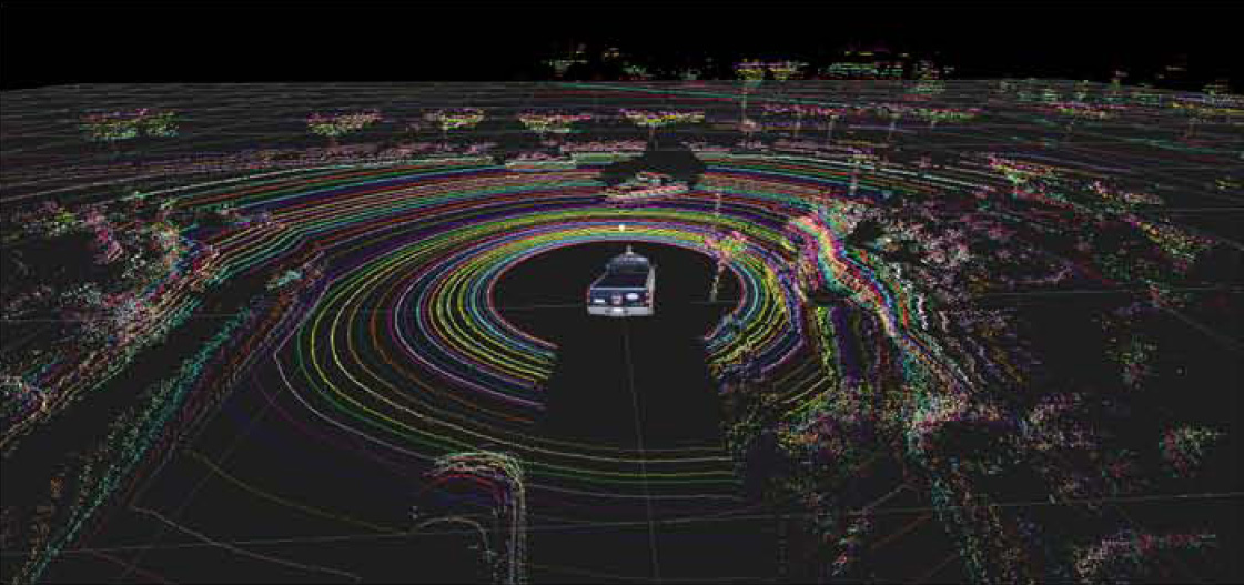
Figure 4. While LIDAR offers excellent depth data, its vertical resolution is limited, complicating identification of objects (Credit: Velodyne)
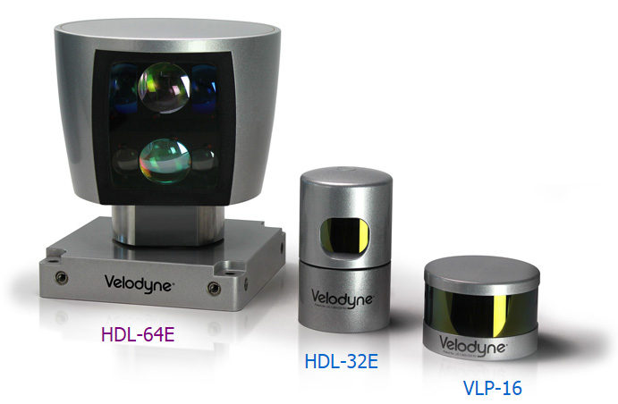
Figure 5. LIDAR sensors with (left to right), 64, 32, and 16 pixel vertical resolution (Credit: Velodyne)
The refresh rate of a rotating LIDAR system is another limitation. Sensors on the market today rotate at approximately 10 Hz; if they are tracking a vehicle traveling at 60 mph, that vehicle travels roughly 880 feet between rotations. Increasing the LIDAR sensor's rotation introduces motion artifacts that must be corrected; these artifacts are similar to how a rolling camera shutter distorts a fast moving object in a picture.
In addition, LIDAR is subject to environmental conditions. Rain, snow, fog, and even car exhaust affect the return signal and therefore the quality of the sensed distance information. LIDAR performance is also degraded when the transmitter or receiver is behind tinted glass such as the windshield of a car. Some of these issues can be mitigated by increasing the illumination signal strength, but doing so creates other challenges related to power consumption and heat dissipation.
The reflection factor of the tracked object can also limit LIDAR performance. The reflectivity of pavement, for example, is less than that of vehicles, which means that a car might be seen, but a pothole at half the distance may be missed. Similarly, a person with light-colored clothes may be seen at longer distances than one in dark clothes.
Stereo Vision
First generation automotive vision safety systems are largely based on a single camera, also known as a monocular vision system. These monocular systems are proving very successful and inexpensive in addressing common driving problems, such as front collisions and inadvertent lane departure. They have some critical limitations, however, which limit their applicability in more fully autonomous driving situations. (See sidebar "A Closer Look at Automotive Monocular Vision Algorithms".)
Stereo vision is a passive solution that has all the capabilities of a monocular vision solution, but also provides depth information like LIDAR and RADAR systems. Using two cameras, it calculates distance in a manner similar to that of the human visual system. By observing the displacement between two images, the distance to an object is discerned; objects that are closer have a greater disparity in the two images.
Stereo vision offers a variety of benefits over monocular camera systems and LIDAR solutions. A stereo vision depth map simultaneously enables greater density depth maps, higher refresh rates, and lower costs than LIDAR and RADAR systems. Detailed depth maps from stereo vision enable terrain mapping, generic obstacle and debris detection, and “free-space” (parking lots, construction zones, etc) driving; current monocular camera systems are unable to create these depth maps, making them unable to support these environments. In the event a camera is blinded, a stereo system can revert to a monocular mode, providing a level of redundancy not possible with a monocular solution. In addition, developers are able to leverage small, inexpensive camera sensors, which limit the incremental cost and real-estate requirements of the second camera while bringing significant benefits.
In terms of challenges, stereo systems, like monocular systems, require a good-quality image in order to perform well. Poor lighting, dirt, and environmental conditions all impact the accuracy of the generated depth map. Compared with monocular vision, stereo systems bear the added cost of a second image sensor as well as the additional space required for that camera. Stereo vision also requires additional compute horsepower for the two video inputs, which increases processor and system memory costs. Alignment and calibration of the two cameras also requires special effort.
One notable demonstration of monocular and stereo vision’s potential was shown by VisLab researchers in 2010 when they operated four autonomous vehicles about thirteen thousand kilometers from Parma, Italy to Shanghai, China. Building on twenty years of research and development by the team, this intercontinental, cross-country journey required vehicles to autonomously navigate urban, rural, highway, and open-space terrain in a variety of weather, environmental, and geographic conditions. This extreme real-world road trip amassed terabytes of data which has been used to further refine the group’s algorithms. Since then, they have demonstrated two more vehicle models that show this technology seamlessly integrated into vehicles.
Far Infrared Sensors
An individual running on the side of the road at night provides a challenge to systems that operate on visible light, and represents a serious risk factor of causing an accident. These individuals are nearly impossible for a traditional camera sensor – one that detects visible light – to see at night. To address this limitation, some car manufacturers are integrating far-infrared (FIR) sensors that provide a heat map of the scene. In environments where a person is significantly warmer than the ambient night air, FIR sensors can highlight the individual and enable pedestrian detection algorithms to more easily detect him or her (Figure 6).
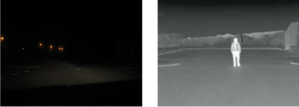
Figure 6. An example of person standing after dark, sensed in the visible spectrum (left) and the far infrared spectrum (right). Note the difference in temperature of the head and legs versus the torso in the FIR image.
However, as with all of the technologies discussed in this article, FIR sensing has its limitations. In warm climates and summer months, the difference in temperature between the person and the environment is often too small to be detected by FIR sensors. Similarly, if an individual is outside for a long period of time, the difference in temperature may be less apparent. Bulky clothing, scarves, and gloves can also distort the shape of an individual or hide the thermal disparity between the person and the ambient air. These challenges, coupled with the low resolution of far-infrared sensors (discussed next), complicate FIR pedestrian detection algorithms.
The physical design of FIR sensors – technically called microbolometers – is also limiting. Target FIR wavelengths are 7-14 µm, so pixels are 20-40 µm in size, or as much as 60x the size of those in an automotive image sensor that captures visible light. As a result, FIR sensor resolution is much lower than that of a regular camera even though the sensor is larger. For example, newer FIR cameras have a resolution of only 320×240 pixels (Figure 7). FIR cameras also require a more expensive assembly process than a traditional camera; they must be vacuum packed to minimize the effects of heat transfer between pixels that occurs through air.
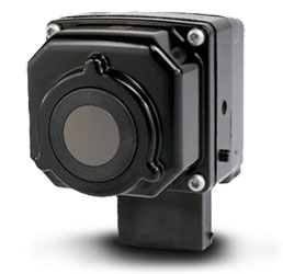
Figure 7. FIR automotive thermal imager (Credit: FLIR)
Automotive Innovations in CMOS Image Sensors
Complementing the innovations in computer vision algorithms, improvements are also being made in the image sensors that capture the video frames. For example, to enable better low-light performance, individual pixels on automotive sensors are currently roughly10x larger than those found in a smartphone (6×6 µm2 vs. less than 2×2 µm2); a larger pixel allows more light to be collected, and also enables greater dynamic range. Sony, for example, recently announced an automotive camera sensor capable of capturing high-resolution color images below 0.005 lux, effectively enabling objects to be seen on a moonless night.
Other techniques are also increasing the amount of light captured by image sensors. One method involves raising the threshold of the sensor's IR cutoff filters in order to let in more light. Another emerging technique is to only use alternating red and clear filters above the sensor's pixels, as opposed to the traditional "Bayer Pattern" red/green/blue filter array. Green and blue filters block some of the photons that would otherwise reach the sensor; replacing them with clear filters lets more light reach the sensor. Red filters are retained in order to discern critical red-colored objects such as brake lights, tail lights, and stop signs. The resulting image – consisting of red and shades of gray– may not be ideal for viewing by people, but can be effective for computer vision algorithms, which primarily use brightness information.
Image sensor dynamic range –the ability to see detail in both dark and bright regions – is also improving. For example, in night driving, high dynamic range (HDR) techniques are helpful in identifying car outlines even in the presence of bright headlights. HDR also helps with driving during the day, when a vehicle's camera might otherwise be blinded by glare. Some emerging sensors adjust the exposure time on a line-by-line basis within the image; this technique sacrifices some image resolution, but this may be acceptable since many of today’s sensors offer high resolution. Another technique combines images taken at different exposure settings to create an optimum image; this approach retains high resolution but sacrifices frame rates, which can cause problems for fast-moving scenes.
Sensor Fusion
Despite rapid innovation, each of the technologies discussed in this article has intrinsic shortcomings that limit its use as a standalone technology for ADAS and emerging self-driving cars. By fusing legacy and emerging vision-based sensor technologies, their individual weaknesses are mitigated and the vehicles achieve greater safety and system-level redundancy.
For example, where vision techniques may be impaired by inclement weather, RADAR solutions thrive. Detailed depth maps from stereo systems can improve the reliability and accuracy of monocular vision systems. And while FIR sensors have poor resolution, their information can be superimposed on a scene captured by high-resolution visible light sensors. Furthermore, FIR sensors coupled with vision sensors can identify regions of interest that simplify the vision analysis of more detailed visible light images. And while monocular vision solutions can be fooled by distance, they are great at recognizing objects; RADAR has the opposite characteristics.
By combining monocular and stereo vision automotive solutions with other automotive sensors, detailed maps, and inter-vehicle communications capabilities, a more complete picture of the external world can be formed. And as this external picture improves, further automation of the control functions of a vehicle – acceleration, braking and steering – can occur, bringing with it greater safety and autonomy in a wider variety of driving conditions and situations.
Sidebar: Environmental Challenges
While fresh white stripes on a newly paved blacktop are extremely easy to detect, faded, restriped, or otherwise low-contrast markings can be difficult for computers (and humans!) to identify. In rain, snow, and fog, recognizing objects, including painted lines on the road, becomes even more difficult. In addition to changing the appearance of objects, poor weather and road conditions can result in water, snow, leaves and dirt on the windshield, reducing the performance of the camera, which is often located behind the rear-view mirror (Figure A). Similarly, windshield glass damage from a stone strike can negatively impact the vision system.
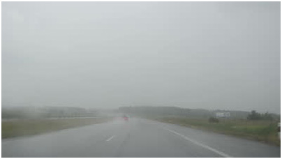
Figure A. Inclement weather can make it difficult for vision systems to detect road markings and other vehicles
Road conditions complicate vision recognition in other ways. Botts’ dots (also called buttons and turtles) are non-reflective raised pavement markers used for lane-change detection, and are only a few image sensor pixels in size. It can therefore be difficult to differentiate them from sensor noise artifacts, especially when looking dozens of feet down the road or when striving to identify them at night (Figure B). For a vehicle traveling in the fast lane on a multi-lane highway, a speed limit sign on the side of the road may only appear for a few frames with sufficient resolution to identify and read the speed before the sign passes out of the camera’s field of view. Some streets are also “cluttered” with shadows, tar and skid marks, and cracks that can confuse vision systems.
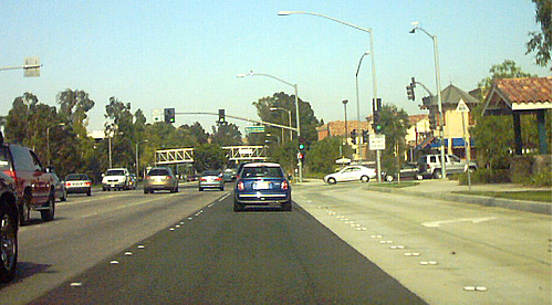
Figure B. Repaving artifacts and Botts' dots can provide challenges to Lane Keeping Assistance (LKA) and Lane Departure Warning (LDW) ADAS systems
Humans struggle to see in difficult lighting conditions, so it is not surprising that such situations also pose challenges for computer vision systems. Just as it takes our eyes some time to adjust when moving between bright and dark conditions – when entering or exiting a parking structure or tunnel on a sunny day, for example, or when an oncoming car has its bright headlights on at night – cameras and their sensors also need to make adjustments. Even in daytime, camera images can be “washed out” if the sun is within about 15 degrees of the horizontal plane of the camera. At night, cars are largely recognizable only by their headlights and taillights. At longer distances, a headlight may only be a few pixels in size, which can be difficult to differentiate from noise.
Similarly, optical illusions can be troubling for computer vision systems. For example, at night it can be difficult to determine whether three "seen" headlights are generated by a car and nearby motorcycle, by two vehicles following each other with one vehicle partially obscured, or by two vehicles where one has a broken headlight. On a wet surface, the tire track of a preceding vehicle may be more visible than the actual road markings; these tire tracks can be falsely identified as lane markings in such conditions.Reflections from your own or another vehicle can also create an optical illusion. (Figure C) If the vision system sees and uses a reflection of your own vehicle, for example, calculating the distance to the “reflection” could dangerously double the expected time-to-collision over what it is in reality or it could be incorrectly identified as a vehicle traveling in the opposite direction. Similarly, a towed vehicle or a vehicle in a “car carrier” can be incorrectly identified as a vehicle traveling in the wrong direction.
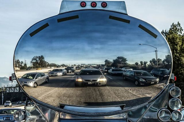
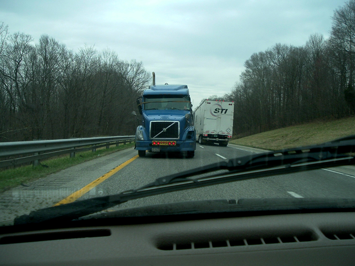
Figure C. Optical illusions such as the reflection from a tank vehicle (top) can create problems for vision systems. In the bottom picture, a towed semi looks like a vehicle traveling in the opposite direction; it is in fact no threat and is going the same direction as other traffic. (Credit: Chris Valle, Bob Canada)
Vision systems are also impacted by vehicle condition. Towing a trailer or carrying a heavy load can incorrectly orient the camera – leaving the vehicle pointing slightly upward – which can throw off distance calculations or degrade features such as lane-keeping assist that looks for lane markers. Furthermore, the load and braking ability of a vehicle needs to be taken into account when the vision systems are tied to automatic braking systems to insure that vehicles have enough time to stop.
Sidebar: A Closer Look at Automotive Monocular Vision Algorithms
A brief look at forward collision avoidance and automatic cruise control systems provides a good example of some of the limitations of monocular vision systems. For these safety features, a monocular vision system has two fundamental steps: identify a vehicle, and determine the distance to the vehicle.
To identify a vehicle, vision and pattern recognition algorithms narrow down a region of interest (a road) and then identify vehicles in that region of interest through certain common object characteristics. A car, for example, usually has symmetry, certain geometric proportions, two wheels when seen from the back, brake lights and tail lights, etc. Computer vision and pattern detection algorithms can identify these object characteristics in a video stream.
While these descriptions work well in many situations, there are scenarios in which these object characteristics don’t work. Examples include a vehicle being towed, an object – mattress, couch, trash bag, debris, etc. – that has fallen from a vehicle, or a vehicle turned sideways and blocking a road. Unless a monocular vision system is trained to see these objects on the road, they are effectively blind to them when they do occur.
In other cases, the camera may simply not see the threat due to a sharp turn or because the threat is in the camera’s blind spot, at which point it is inappropriately eliminated from analysis consideration (Figure D).
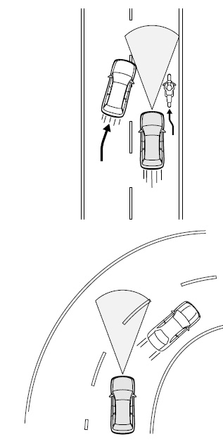
Figure D. If a vehicle or object is too close, it may not be in the camera’s field of view. A similar problem occurs if the road direction changes suddenly. Not seeing the potential conflict, the vehicle could accelerate, causing an accident (Credit: Subaru Instruction Manual, “Adaptive Cruise Control”)
Accurately assessing these changes in threats is important. The system needs to figure out whether a true threat exists (e.g., the car ahead has disappeared while going around a sharp turn) or not (e.g., the car has turned off the road).
Once an object is identified, algorithms then determine the distance to the vehicle (Figure E). In a research paper, MobilEye outlined an approach that determines the distance by determining where on the image sensor the wheels of the car contact the road. If the vehicle is close, the wheels are farther down on the image; farther away, the wheels show up higher in the image. However, this perspective-based approach (called inverse perspective matching) can be adversely affected by optical illusions.
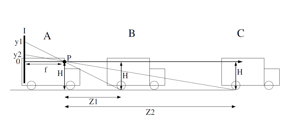
Figure E. Determining the distance Z to a vehicle involves identifying where the object shows up on the image sensor I (P represents the camera and f is the focal length [not drawn to scale]). If measuring to the wheels (i.e. H is large), good accuracy can be achieved. However, if measuring to the brake lights of the leading vehicle or to something in the plane of the camera (i.e., H is small), distance accuracy is reduced (Credit: MobilEye)
For example, a vehicle being towed on a flatbed truck may be interpreted as a vehicle farther away, since the wheels are higher up (Figure F). And if the system calculates the distance to the brake lights (another generally effective approach, since wheels are sometimes difficult to see if a vehicle is following closely or in inclement weather), this technique can be a problem for a vehicle with a long flatbed where the lights are much farther away than the back of the vehicle (Figure G); an example of this is a tow truck, where the tail lights are often put high near the cab, since they could otherwise be blocked by a towed vehicle. In this case, the time to collision may be shorter than what the system thinks it is.
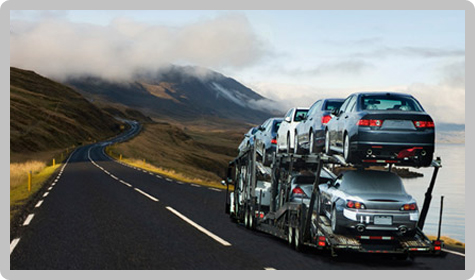
Figure F. A vehicle in a car carrier can be incorrectly identified as a car in the distance, since it is higher up. Or the vision system might mistakenly decide that a hill is coming up, resulting in unexpected acceleration. (Picture credit: ABC Autoshipping)
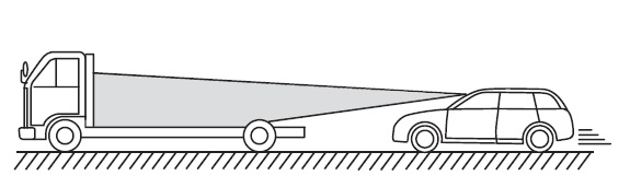
Figure G. Under some circumstances, a monocular vision system could identify a potential threat as farther away than it really is, increasing the chance of an accident. (Image credit: Subaru Instruction Manual, “Adaptive Cruise Control”)
Keep in mind, too, that a small change at the sensor represents a larger change in the real world. This disparity creates ambiguity and inaccuracy when calculating distance. In the case of measuring to brake lights rather than wheels, the angle between the camera’s horizon and the brake lights becomes narrow, increasing the ambiguity and inaccuracy. Yet another challenge is that terrain changes can create false perspectives, resulting in inaccurate distance measurements. Despite these challenges, monocular vision algorithms provide benefits in many conditions and are rapidly becoming standard safety features on cars.
Michael McDonald is an autonomous car enthusiast and consultant for the Embedded Vision Alliance. Through his company, Skylane Technology Consulting, he provides marketing and business development services for technology companies. He can be reached at www.linkedin.com/in/mcdonaldmichael.