
by Michael Tusch
Founder and CEO
Apical Limited
This article was originally published at EDN Magazine. It is reprinted here with the permission of EDN. It was adapted from Michael's technical article on the Embedded Vision Alliance website.
Part 1 of this article looks at examples of embedded vision and how the technology transition from elementary image capture to more robust image analysis, interpretation and response has led to the need for more capable image sensor subsystems.
In any review of image sensor technology, it's often important to discuss so-called HDR (High Dynamic Range) or WDR (Wide Dynamic Range) sensors. Many embedded vision applications (as with photography and other image capture applications in a more general sense) require robust functionality even with challenging real-life scenes. HDR and WDR mean the same thing –it's just a matter of how you use each axis of your dynamic range graph. I'll employ the common terminology "HDR" throughout this discussion.
Cameras, even high-end DSLRs, aren't often able to capture as much information in high contrast scenes as our eyes can discern. This fact explains why we have rules of photography such as "make sure the sun is behind you." Although conventional image sensors struggle in such conditions, the industry has devoted significant work over many years to developing HDR sensors that extend the raw image capture capability. The reliability of the image capture component is, of course, one key element of the overall system performance.
The dynamic range (DR) of the sensor is the ratio of the brightest pixel intensity to the darkest pixel intensity that the camera can capture within a single frame. This number is often expressed in decibels (dB), i.e.,
DR in dB = 20 * log10 (DR)
The human eye does very well with respect to dynamic range and, depending on exactly how the quantity is measured, is typically quoted as being able to resolve around 120 to 130 dB (i.e., ~20 bits) in daytime conditions.
Image sensors are analog devices that convert pixel intensities to digital values via an analog-digital converter (ADC). The bit depth of the output pixels sets an upper limit on the sensor's dynamic range (Table A). In reality, the maximum dynamic range is never quite achieved, since in practice the noise level takes up to ~2 bits off the useful pixel range.
|
Type of sensor |
Bits/pixel |
Maximum intensity levels recorded |
Maximum sensor dynamic range (dB) |
|
Very low-cost standard |
8 |
256 |
48 |
|
Average standard |
10 |
1024 |
60 |
|
Higher quality standard |
12 |
4096 |
72 |
|
HDR |
16 |
65536 |
96 |
|
HDR |
20 |
1048576 |
120 |
Table A. The dynamic range potential of various image sensor types
Standard CMOS and CCD sensors achieve up to ~72 dB dynamic range. This result is sufficient for the great majority of scene conditions. However, some commonly encountered scenes exist which overwhelm such sensors. Well-known examples are backlit conditions (i.e., a subject standing in front of a window), outdoor scenes with deep shadows and sunsets, and nighttime scenes with bright artificial lights (Figure B).

Figure B: This backlit scene has a dynamic range of around 80 dB.
Such scenes typically exhibit a dynamic range of around 100 dB and, in rare cases, up to 120 dB (Figure C). If captured with a conventional sensor, the image either loses detail in shadows or has blown-out (i.e., clipped, also known as "blooming") highlights.
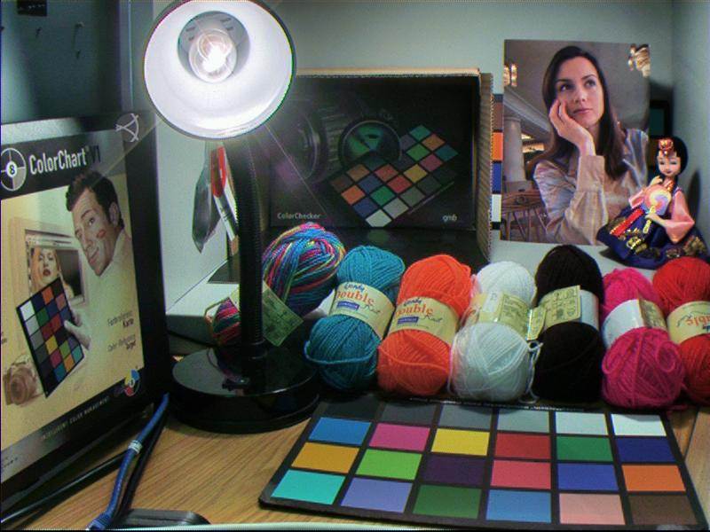
Figure C: This high-contrast scene has a dynamic range of around 100 dB.
Numerous attempts have been made to extend standard CMOS and CCD image sensor technologies, overcoming the limitations of pixel sensitivity and ADC precision, in order to capture such scenes. Pixim developed the first really successful HDR sensor, based on CCD technology, and it was the industry standard for many years. However the technology, which effectively processes each pixel independently, is somewhat costly.
More recently, other vendors have concentrated on sensors constructed from more conventional CMOS technology. Numerous different solutions are available; the remainder of this essay will survey the main vendors and the techniques that they employ.
Available solutions
Multi-frame HDR is an HDR method that does not rely on custom CMOS or CCD technology. Acting as a sort of video camera, the sensor is programmed to alternate between long and short exposures on a frame-by-frame basis, with successive images blended together by the image sensor processor (ISP) in memory to produce a single HDR image (Figure D). If the blending algorithm is robust, an exposure ratio multiple of around 16 is comfortably achievable, adding an extra 4 bits to the single-exposure dynamic range. For example, by using multi-frame HDR, a 12-bit sensor-based system can produce images characteristic of a 16-bit sensor.
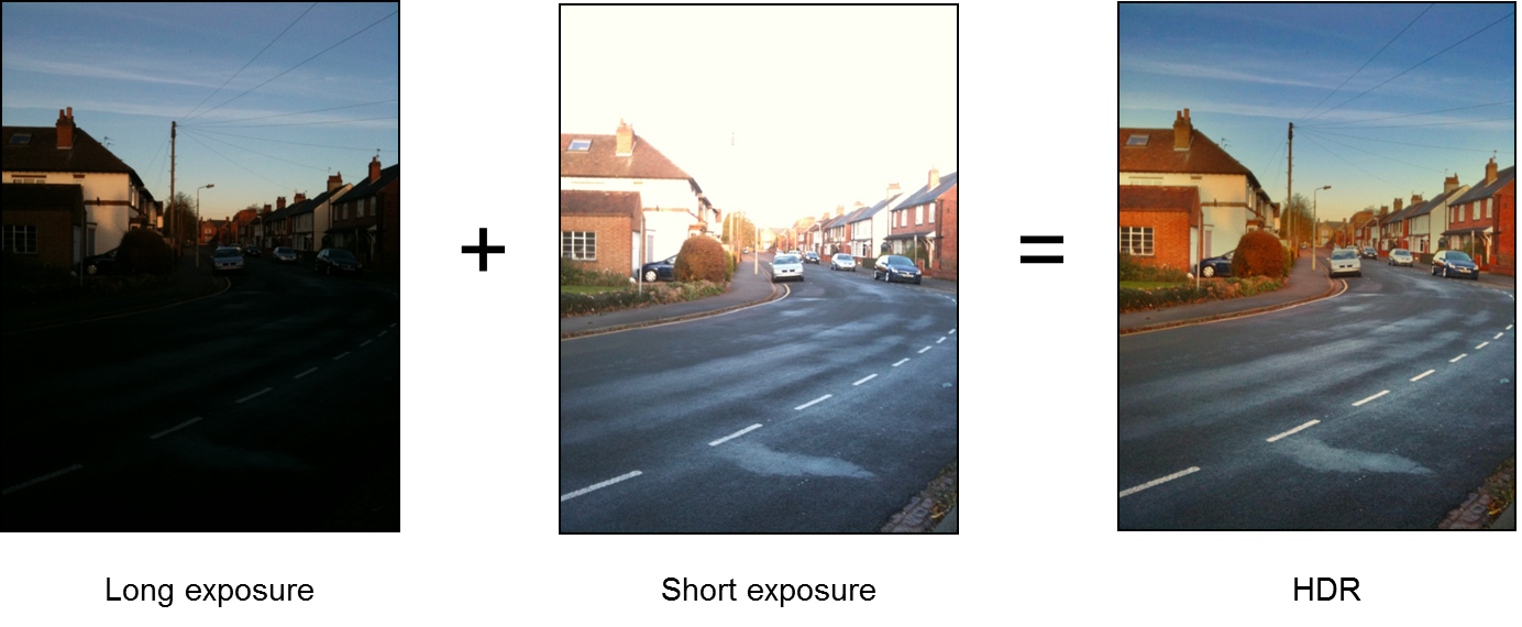
Figure D: Blending together short- and long-exposure versions of a scene creates a multi-frame HDR result.
As with all HDR technologies, there is a catch. In this particular case, it is the potential generation of motion artifacts, most noticeable as "ghosting" along the edges of objects that have moved between the two frames. Such artifacts are very expensive to even partially eliminate, although processing in the ISP can significantly suppress their appearance. Further, the effective frame rate is reduced. If the input frame rate is 60 fps, the output can remain at 60 fps, but highlights and shadows will exhibit an effective frame rate closer to 30 fps, and mid-tones will be somewhere between 30 and 60 fps depending on how clever the blending algorithm is.
A related approach is employed by the AltaSens A3372 12-bit CMOS sensor, which uses a "checkerboard" pixel structure, wherein alternating Bayer pattern (RGGB) quad-pixel clusters are set to long- and short-exposure configurations (Figure E). In HDR scenes, the long-exposure pixels capture dark information, while short-exposure pixels handle bright details.
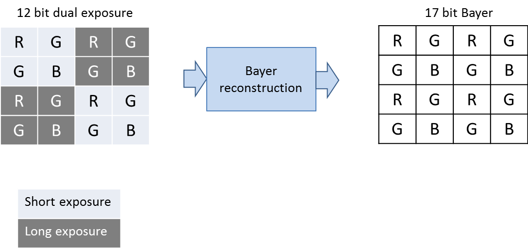
Figure E: The AltaSens A3372 checkerboard array devotes alternating quad-pixel clusters to capturing dark and light scene details.
Long exposure delivers improved signal-to-noise but results in the saturation of pixels corresponding to bright details; the short exposure pixels conversely capture the bright details properly. Dynamic range reaches ~100 dB. The cost of HDR in this case is the heavy processing required to convert the checkerboard pattern to a normal linear Bayer pattern. This reconstruction requires complex interpolation because, for example, in highlight regions of an HDR image, half of the pixels are missing (clipped). An algorithm must estimate these missing values.
While such interpolation can occur with remarkable effectiveness, some impact on effective resolution inevitably remains. However, this tradeoff is rather well controlled, since the sensor only needs to employ the dual-exposure mode when the scene demands it; the A3372 reverts to non-HDR mode when it's possible to capture the scene via the standard 12-bit single-exposure model.
A very different HDR method is the so-called "companding" technique employed by sensors such as Aptina's MT9M034 and AR0330, along with alternatives from other vendors. These sensors use line buffers to accumulate multiple exposures (up to 4, in some cases) line-by-line. The output pixels retain a 12-bit depth, set by the ADC precision, but those 12 bits encompass up to 20 (or more) effective bits of linear intensity data. Companding is conceptually similar to the way that gamma correction encodes 2 bits of additional data in a color space such as sRGB. Inverting this non-linear data structure enables obtaining an HDR Bayer-pattern image.
This method produces the highest dynamic ranges; one vendor claims 160 dB. But it again comes with associated costs. First, the data inversion relies on a very accurate and stable knowledge of where the various exposures begin and finish. In practice, imperfections lead to noise at specific intensity levels that can be hard to eliminate. Second, the sequential exposures in time create motion artifacts. These can be suppressed but are difficult to remove. Standard techniques for flicker avoidance (such as "beating" with the 50Hz or 60Hz flicker of indoor lighting) also don't work when more than one exposure time exists.
Yet another HDR sensor implementation is the dual-pixel structure employed by OmniVision in sensors such as the OV10630. It consists of a non-Bayer array of pixels made up of two physically different types: a "dark" pixel and a "bright" pixel, which can be of different sizes. The dark pixels are more sensitive to light and therefore handle dark areas well, with good signal-to-noise. Conversely, the bright pixels are less light-sensitive and therefore don't saturate as readily in bright regions.
In principle, the dual-pixel approach is a very "clean" HDR technology. It avoids motion artifacts and requires no complex non-linear processing. Penalties include the fact that two pixels are blended into one, so the effective resolution is half of the actual resolution. The dual-pixel structure is also more costly on a per-pixel basis, and the output raw pixel pattern cannot be processed by standard ISPs.
More generally, each of the sensor types described in this discussion requires a different image-processing pipeline to convert its captured images into a standard output type. This fact means that it is not typically possible to directly connect an HDR sensor to a standard camera ISP and obtain an HDR result. Figure F shows the pipelines for Bayer-domain processing of the multi-frame AltaSens- and Aptina-type HDR sensors' raw inputs. Standard processing is possible subsequent to color interpolation.
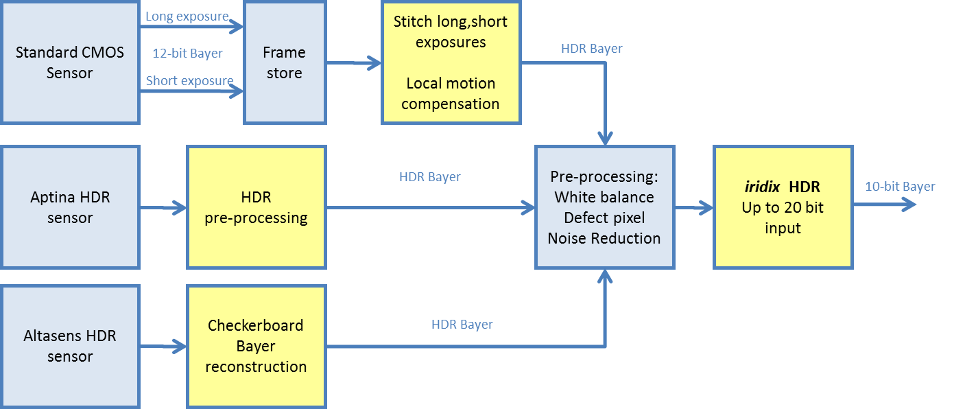
Figure F: The image processing flow varies depending on what type of HDR sensor is being employed.
Obtaining genuine HDR imagery is also not just a matter of leveraging an HDR sensor coupled with an HDR ISP. For scenes with dynamic range beyond 100 dB, optics also plays a central role. Unless the lens is of sufficient quality and the optical system has the necessary internal anti-reflection coatings to prevent back-reflection from the sensor, it is impossible to avoid flare and glare in many HDR scenes, creating artifacts that effectively negate much of the sensor's capture capabilities. To put it simply, building a HDR camera suitable for the full range of scene conditions is not inexpensive.
In conclusion, a variety of sensor and ISP technologies exist for capturing and processing HDR imagery. They all involve some kind of image quality trade-off in exchange for the extended dynamic range, either in resolution or in time. It is worth remembering that although the technology may be elaborate, the purpose is simply to extend effective pixel bit depth and reduce noise. To see this, compare the images shown in Figure G.
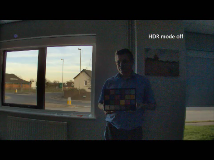
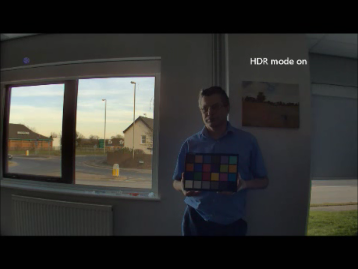
Figure G: A comparison of two images reveals HDR shadow strengths.
The first image was captured using a 12-bit CMOS sensor in normal mode. The second image harnesses the exact same sensor but employs the multi-exposure mode discussed earlier. The effect of the HDR mode closely resembles that of noise reduction. In the first image, strong local tone mapping is used to increase the digital gain so that shadows are visible, while exposure is kept low enough to avoid highlight clipping. This technique in effect captures the window area at ISO 100 and the shadow area at ISO 3200, and it does not require any non-standard capture technology. The HDR image, conversely, obtains the same exposure values for shadows and highlights, but this time by varying the exposure times, leading to greater sensitivity and lower noise in the shadow region.
High-performance temporal and spatial noise reduction technology can extend dynamic range by up to ~12 dB. And high-performance dynamic range compression technology can map input dynamic range to a standard output without loss of information. So a standard 12-bit CMOS sensor with good noise reduction can achieve around 84 dB, which is "pretty good HDR", while a 14-bit CMOS sensor with good noise reduction can achieve nearly 100 dB, which is "mainstream HDR". However, HDR-specific sensors are required for truly high dynamic range scenes.
Michael Tusch is founder and CEO of Apical Limited, a UK-based technology company specializing in image and video processing technology. He started his career as a researcher in semiconductor quantum theory at Oxford University before moving to industry, first with the Boston Consulting Group and later holding several technology management positions before founding Apical in 2001.