This article was originally published at Texas Instruments’ website (PDF). It is reprinted here with the permission of Texas Instruments.
Introduction
Cars continue to become smarter and smarter, integrating new and cutting-edge technologies to make the driving experience safer and more enjoyable. With the goal of reducing roadway fatalities, enabling these new advanced driver assistance systems (ADAS) applications takes extensive processing and specialized peripherals while still needing to manage power consumption in a very challenging environment.
Texas Instruments (TI) is wholly committed to the automotive market and offers a broad portfolio to support it, including analog and mixed-signal devices, digital signal processors, microcontrollers, RFID, and digital logic as well as supporting software and tools. Innovative automotive technologies from TI make for a safer, greener and more enjoyable driving experience. Safety is of utmost importance in any automotive application, including ADAS. SafeTI™ design packages help designers meet ISO 26262 functional safety requirements, making it easier for customers to get to market quickly with their safety critical system.
ADAS applications have high demand for compute performance, require small system footprint and need to operate at extreme temperatures. The opposing requirements create a very challenging environment. To deliver maximum compute performance at extreme temperatures while encapsulated in miniature enclosures the parts need to be extremely energy efficient. Cars in Alaska can easily reach subzero temperatures quickly in the winter, while cars in Texas and other hot areas of the world exceed 140 degrees Fahrenheit in the summer. All electronic components have to be able to withstand temperature variations and extremes while still maintaining stringent performance requirements. TI has solutions to meet these extreme needs.
With more than 60,000 products and 900 new parts per year that make up TI’s portfolio, including 130+ new automotive-specific parts, TI has a strong presence in the automotive market. In addition, TI has more than 30 years of experience in the automotive electronics market as well as an exciting roadmap to the future ensuring that TI will be there to support the needs of all vision-enabled automotive applications. Whether it is embedded processors, a full signal chain, interfaces or power, TI has the right solution for ADAS.
Does a car really need vision?
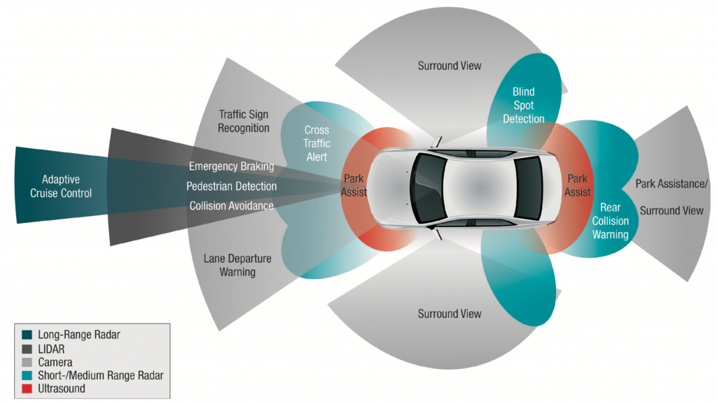
ADAS systems use specialized processors and software to provide real-time information and feedback to drivers based on data captured from sensors positioned inside and outside of vehicle (see Figure 1). ADAS systems are designed to increase the safety of the driver, passengers and pedestrians while also increasing the enjoyment and ease of the driving experience.
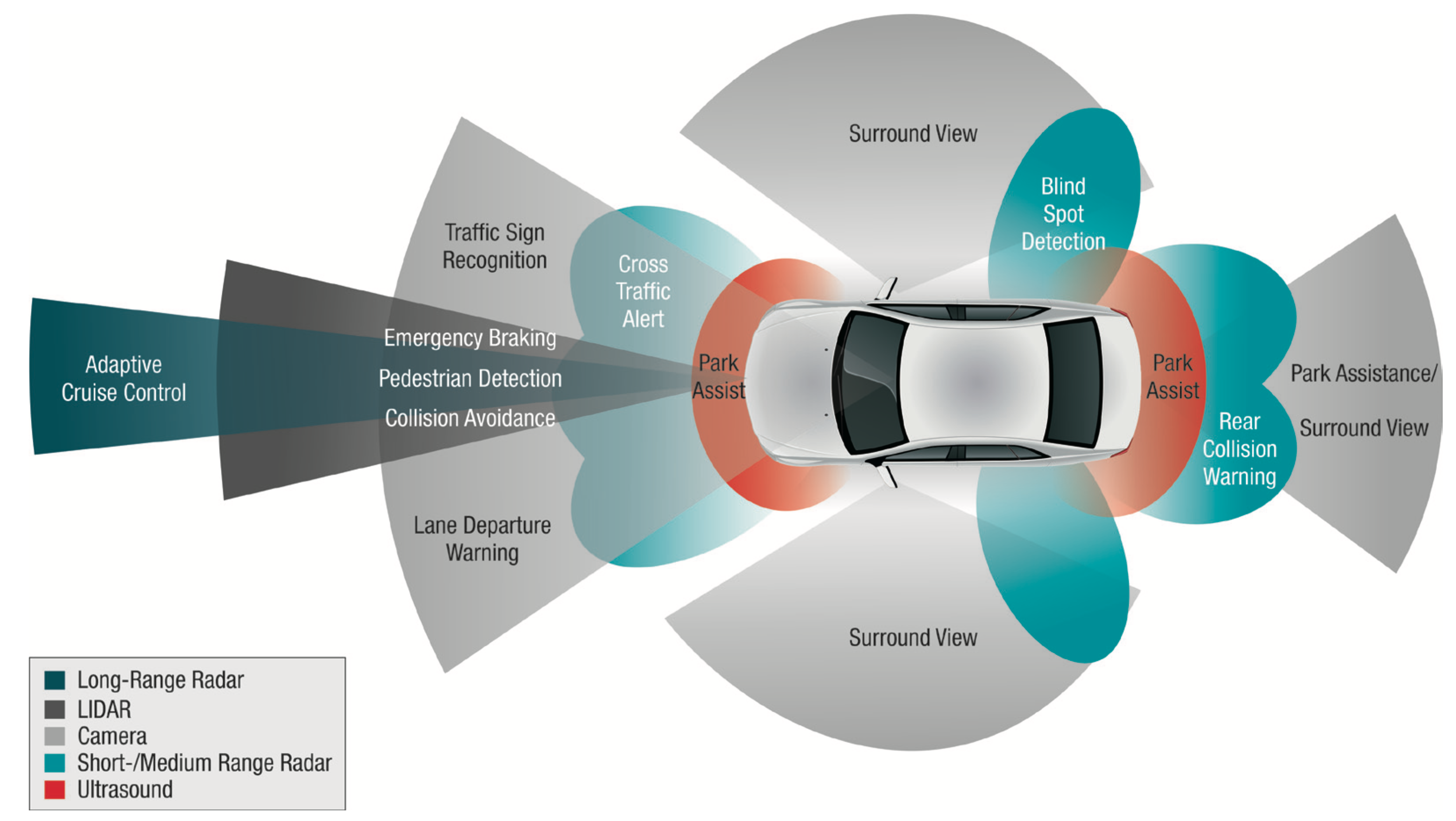
Figure 1: ADAS applications
With the advances in automotive vision taking place now, autonomous cars truly are in the near future. Google announced in August 2012 that they had developed and tested a self- driving car1. They drove over 300,000 miles in their testing with complete computer controls. Daimler has also released plans to develop a driverless car by the year 20202. At CES 2013, Audi demonstrated their version of a self-piloting car that was able to drive itself in a traffic jam as well as negotiating the tight spaces of a parking garage3. Other car manufacturers, like BMW4 and Toyota5, are also in the testing phase of self-driving cars. But none of this is possible without the most advanced automotive vision solutions that are able to reliably deliver real-time processing of visual data at the right cost and power savings.
Front camera ADAS applications
Front camera (FC) systems use either one or two cameras mounted between the rearview mirror and windshield facing forward. With applications like collision avoidance and lane departure warning, FC systems help reduce accidents and fatalities on the road. FC systems using two cameras are able to provide scene depth information to increase the data available therefore accuracy. Next-generation FC systems are integrating as many as five algorithms in the same system at a low power footprint.
Front camera applications may include lane departure warning/lane keep assist, pedestrian detection, road sign recognition, forward collision warning/avoidance and intelligent head beam assistance. Lane departure warning systems for example, monitor the car’s location relative to the lane markings and send a warning signal to the driver if he is drifting. In lane keep assist systems, the vehicle actually corrects the steering for the driver, moving the vehicle back into the lane. Pedestrian detection systems use vision analytics to recognize pedestrians and warn the driver of the potential hazard. Similarly, with traffic sign recognition the vehicle’s camera system is able to recognize road signs and pass on that information automatically to the driver. Forward collision warning and avoidance technology enables the vehicle to automatically track hazards around the vehicle and detect an imminent crash. The vehicle can then send a warning to the driver or, in avoidance systems, take action to reduce the severity of an accident. Advanced front-lighting systems optimize the headlight beam based on road curvature, visibility and weather conditions as well as vehicle speed and steering angle. Other intelligent headlight systems are able to automatically adjust head beams so that the headlights do not blind the driver in an oncoming car.
FC systems typically use high-dynamic range imaging sensors with more than eight bits per pixel and resolutions of WVGA and higher. Figure 2 shows an example block diagram of a single-camera FC system. The single forward-looking imaging sensor in this block diagram sends captured frames into an applications processor where vision analytics are run on the data to provide the vehicle with timely and accurate information on which to base any needed actions, whether it is for lane assist, road sign recognition or forward collision warning.
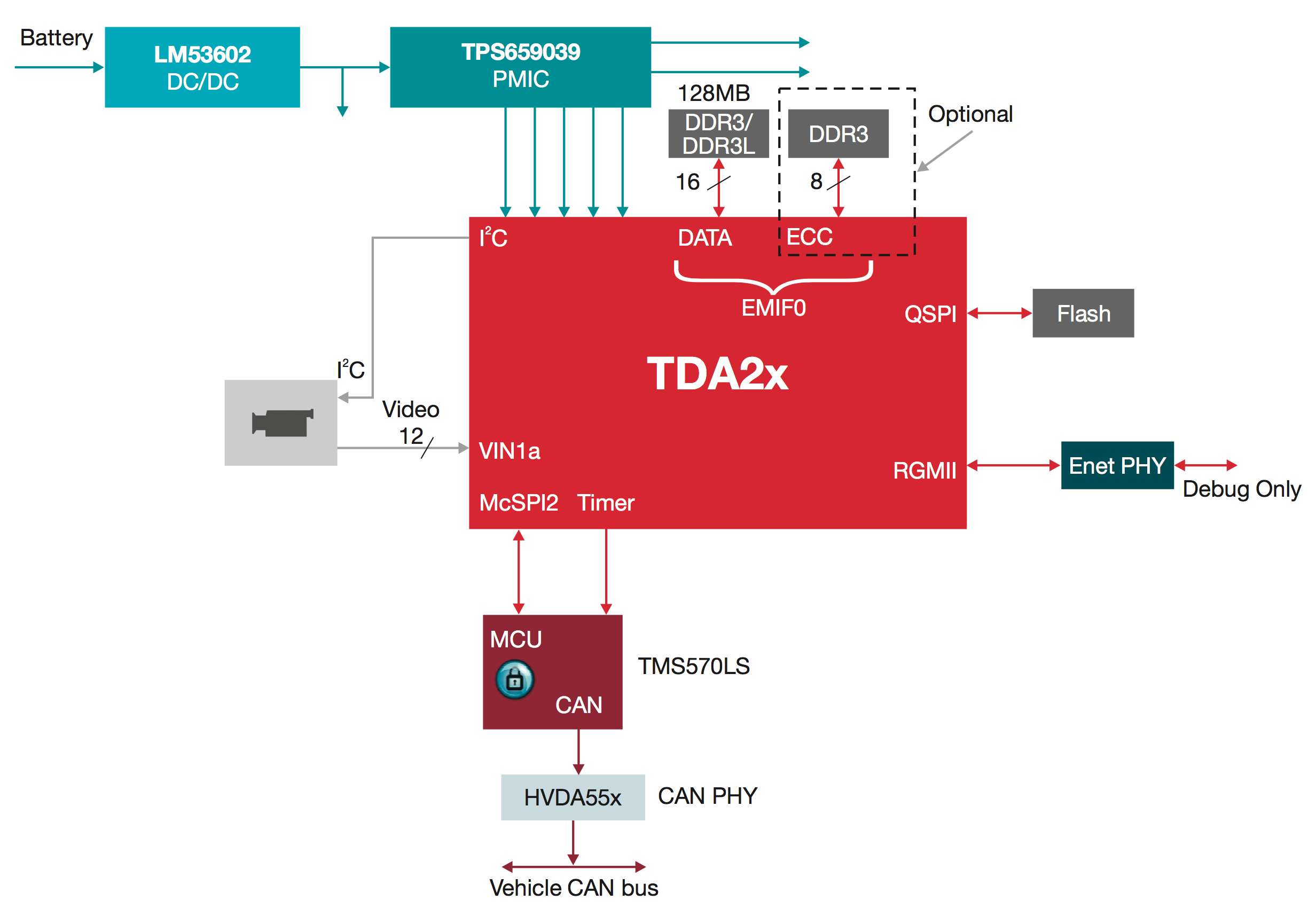
Figure 2: Front view block diagram
Surround view ADAS applications
Surround view (SV) systems present a vast amount of useful information to the driver in real time, with minimum glass-to-glass latency. The 360° view as well as park assist and bird’s-eye view allow the driver to be fully aware of vehicle’s surroundings. For example, the system could allow a driver to see a bicycle that has been left behind a parked car or it can show how close the vehicle is getting to other vehicles when trying to park in a tight spot. In fully automated systems, the vehicle is able to use this information to actually park itself. SV systems increase the safety of operating vehicles by allowing drivers to see objects they might otherwise not see as well as make driving these vehicles easier and more fun. A surround view system typically consists of at least four cameras (front camera, two side cameras on each side of the car and a rear camera) as well as ultrasound sensors (see Figure 1).
SV systems typically require video streams with at least 1280×800 pixel resolution on each camera and a frame refresh rate of 30 fps. The cameras stream video to the central processor either as analog NTSC, digital uncompressed via Low Voltage Differential Signaling (LVDS/FPD-Link) or compressed instead via say Gigabit Ethernet (GbE). The camera streams can then be stitched together to form a cohesive and seamless view around the outside of the car. Outputs from the surround vision system are sent to a heads-up display(s) at VGA or higher resolution. This display makes it easy for the driver to recognize and react to any hazards surrounding his car. Additionally, in the future, 3D rendering could be used for highly realistic surround views. A high-level block diagram LVDS/FPD-Link-based SV system is shown in Figure 3. In this example, five cameras are used to create the bird’s-eye view that can then be fed to a heads-up display or other display within the vehicle. Park assist and automated parking systems use information from the surround view cameras and radar (or sonar) to analyze objects and their distances from the vehicle to enable it to automatically park itself or to provide feedback to the driver to help him safely park the vehicle.
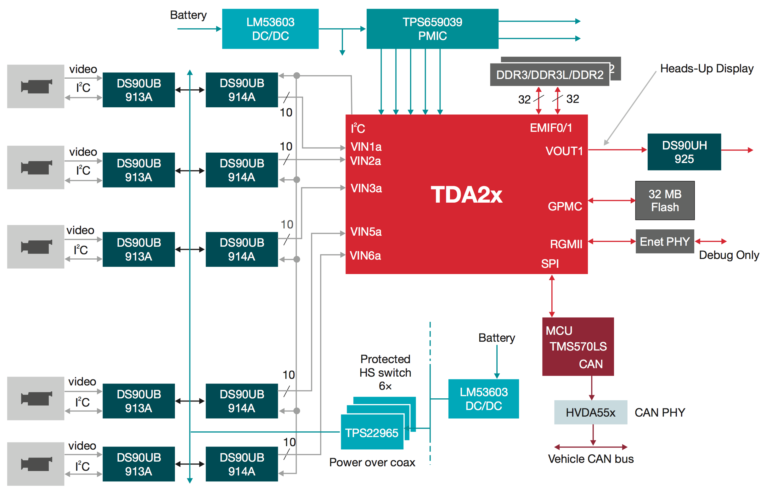
Figure 3: FPD-Link surround view block diagram
Night vision systems are used to extend the driver’s ability to see beyond the vehicle’s headlights at night or in bad weather by using information obtained from near or far infrared sensors. Emerging applications, such as mirror replacement cameras, require multiple imaging sensors as they intend to replace side and rear view mirrors with cameras and displays.
Figure 1 illustrates different types of sensors used in ADAS systems. Once processing at the sensor level is complete, the high-level information can be sent to the central processor or sensor fusion box. The fusion box aggregates and interprets the combined high-level data from each sub-system (i.e., fusing information from front camera system, radar, etc.).
These applications, including front camera and sensor fusion box systems, not only require a high level of real-time data processing but they also typically need to satisfy higher functional safety requirements as their responsibility extends to taking control of some car functions (i.e., steering in case of Lane Keep Assist).
Surround view data flow in detail
Let’s look more closely at an example data ow for a surround view system. Most surround view systems use between four and six external high-resolution, high-dynamic range video inputs. For LVDS-based surround view, this translates to the processor requirement to support four or more camera inputs wider than 8 bits/ pixel. For a surround view system with four cameras, one camera is forward facing and located near the grill at the front of the car, one would be rear facing located on the trunk or hatch of the vehicle, and two are located on the sides of the car, typically one on each side-view mirror (see Figure 1). With a minimum of four cameras, a surround view system is able to interpret and display a full 360° top view image around the vehicle.
In the case of an Ethernet-based surround view, the processor needs to have an integrated Gigabit Ether- net (GbE) with Audio Video Bridging (AVB) support for low-latency streaming and a powerful video decoder capable of decoding four or more MJPEG/H.264 compressed video streams.
Surround view applications require multiple stages of processing. A powerful and fast on-chip interconnect, large on-chip memories and wide DDR interface are required to accommodate the high data bandwidth and low-latency processing of multiple high-resolution video streams (see Figure 4).
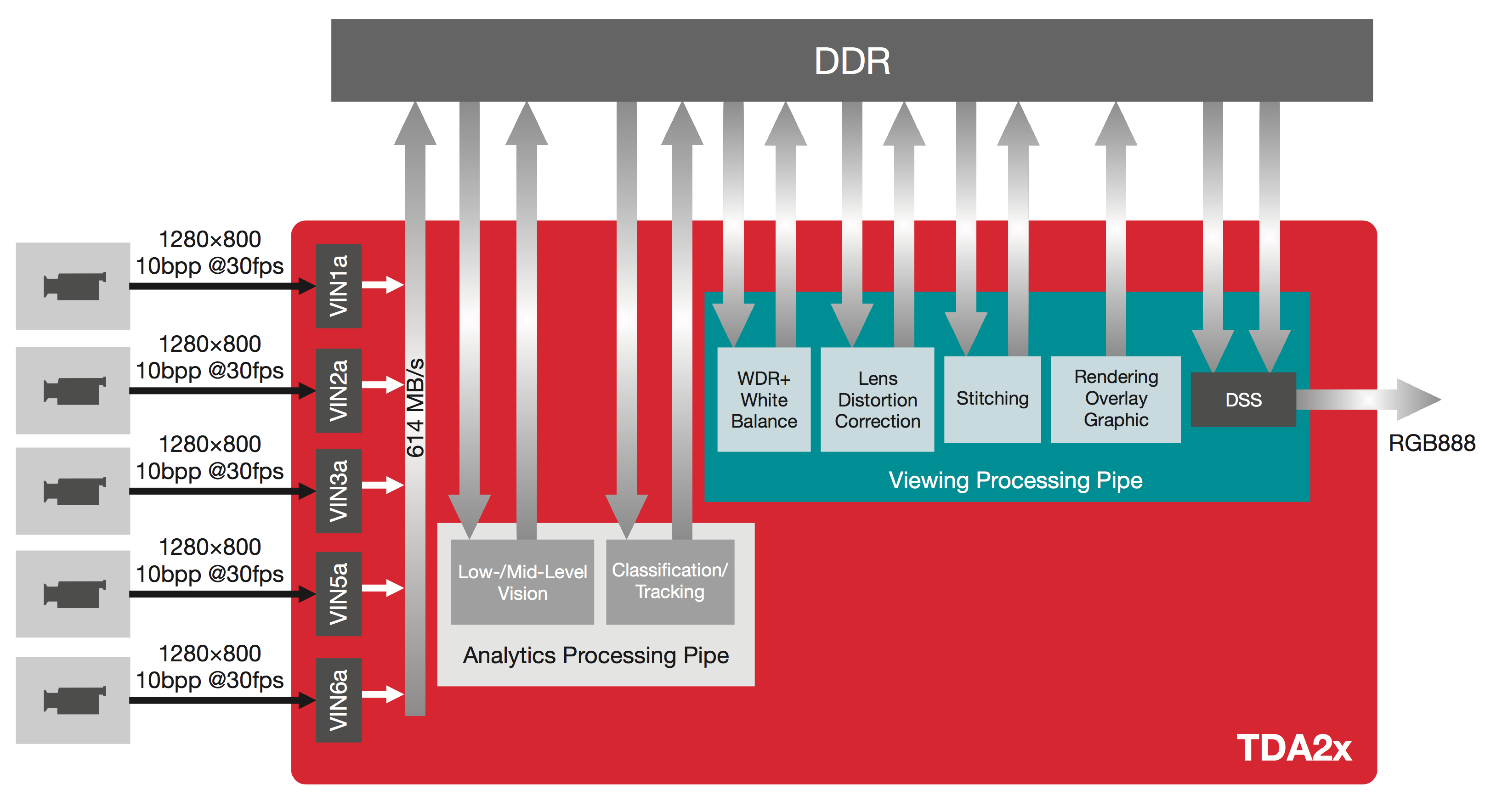
Figure 4: LVDS-based surround view data flow
With the proper memory, interconnects and peripherals in place, the system is ready to process the captured video frames. On high-end surround view systems, captured video frames are typically passed through two processing pipes: a viewing pipe and an analytics pipe. The viewing pipe is preparing captured frames for display to the driver. Because surround view cameras typically have a wide field of view, one of the first viewing pipe processing steps is rectification or Lens Distortion Correction of incoming video. Photometric alignment and stitching frames captured by different cameras are also steps within the viewing processing pipe. The processor also renders graphic overlays onscreen to either indicate backing guides or highlight objects close to the car. The graphic overlays and video data to be shown to the driver are combined inside the Display Sub System (DSS).
Output from the analytic processing pipe is used to alert driver. Functions such as Cross Traffic Alert, Rear Collision Warning or Object Detection can be part of the analytics processing pipe. Therefore, the SoC intended for high-end surround view applications must offer extreme processing power, rendering and video processing capabilities to satisfy analytics and viewing compute demands.
TDA2x SoC brings automotive vision technologies to life
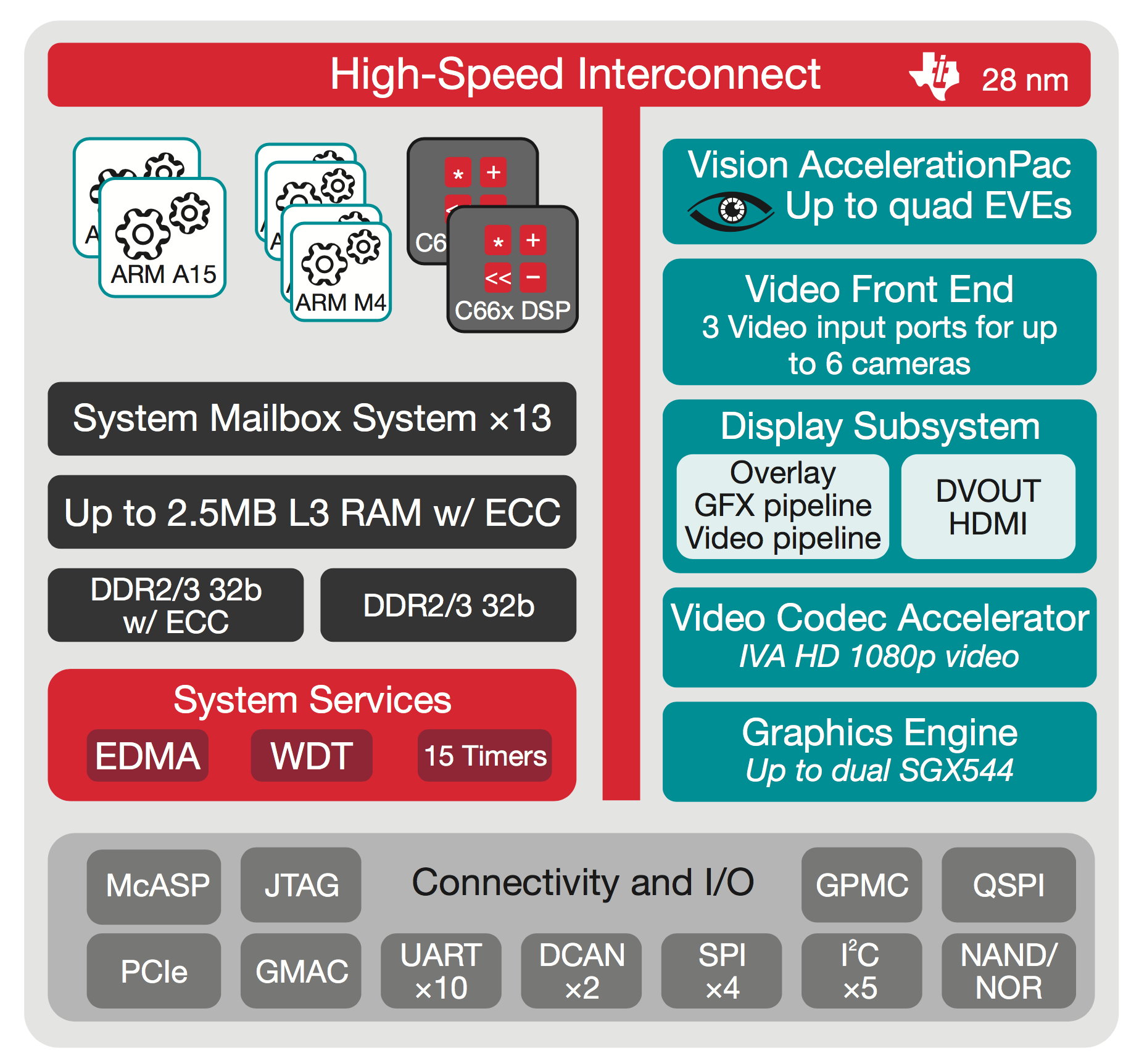
Figure 5: TDA2x SoC block diagram
So what do TI’s TDA2x SoCs bring to the automotive vision market? ADAS systems demand high processing power and peripherals to support real-time vision analytics. TDA2x SoCs deliver this with scalable, highly integrated SoCs consisting of a general-purpose dual-Cortex™-A15, dual C66x DSPs, integrated peripherals and a Vision AccelerationPac to offload vision analytics processing while reducing the power footprint. TDA2x SoCs also include video and graphics for advanced front camera, park assist and surround view applications.
With the TDA2x SoC, TI has efficiently mapped out the ARM general-purpose processing cores to manage core control processing. Mid- to high-level processing is performed by one or more DSP cores optimized for real-time functions such as object detection, and low- to mid-level processing is handled by the Vision AccelerationPac (see Figure 6 for more details.). The Vision AccelerationPac was specifically designed to offload the processing of vision algorithms from the TDA2x DSP and ARM cores, yielding the best performance for low- to mid-level vision processing at the lowest power footprint.
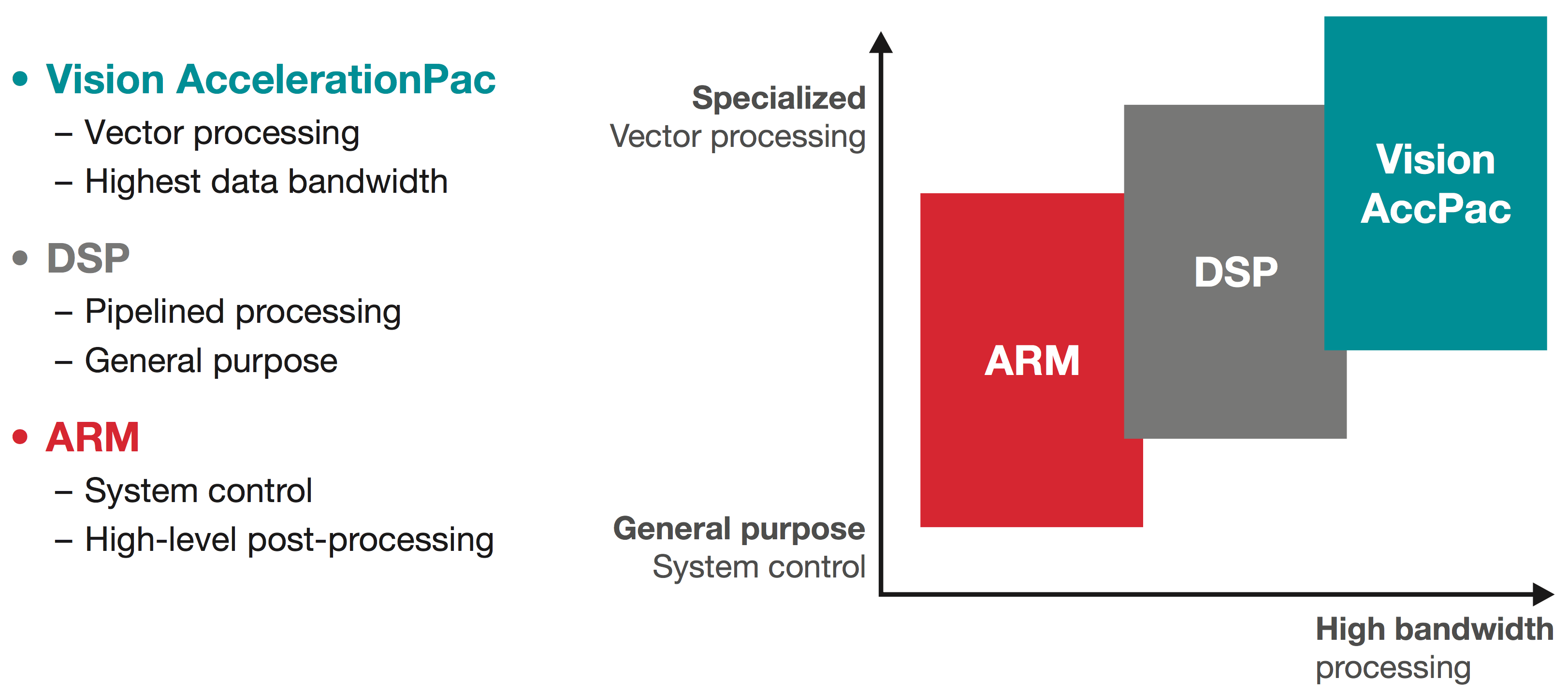
Figure 6: Heterogeneous SoC concept for highest processing performance and power efficiency
This innovative Vision AccelerationPac [consisting of one or more Embedded Vision Engines (EVE)] offloads the vision analytics functionality from the applications processor delivering up to an 8× compute performance increase with respect to the Cortex-A15 at the same power budget. The Vision AcceleratorPac consists of a 32-bit RISC core and a vector coprocessor excelling at low- and mid-level vision processing. With each vector core clocked at up to 650 MHz and operating at 16 MACs per cycle (8 bit or 16 bit), the Vision AccelerationPac is able to deliver over 10.4 GMACs per core, more than 40 GMACs for a quad-EVE system providing outstanding vision analytics processing.
Optimum embedded vision processor architecture should find the best balance between opposing requirements such as raw processing power, thermal dissipation and cost. The scalable TDA2x family of processors is offering this balance with its Vision AccelerationPac achieving highest performance per mW as seen in Figure 7. Vision AccelerationPac combined with C66x DSPs enable ADAS systems to run more than 5 ADAS applications simultaneously at less than a 3W power footprint.
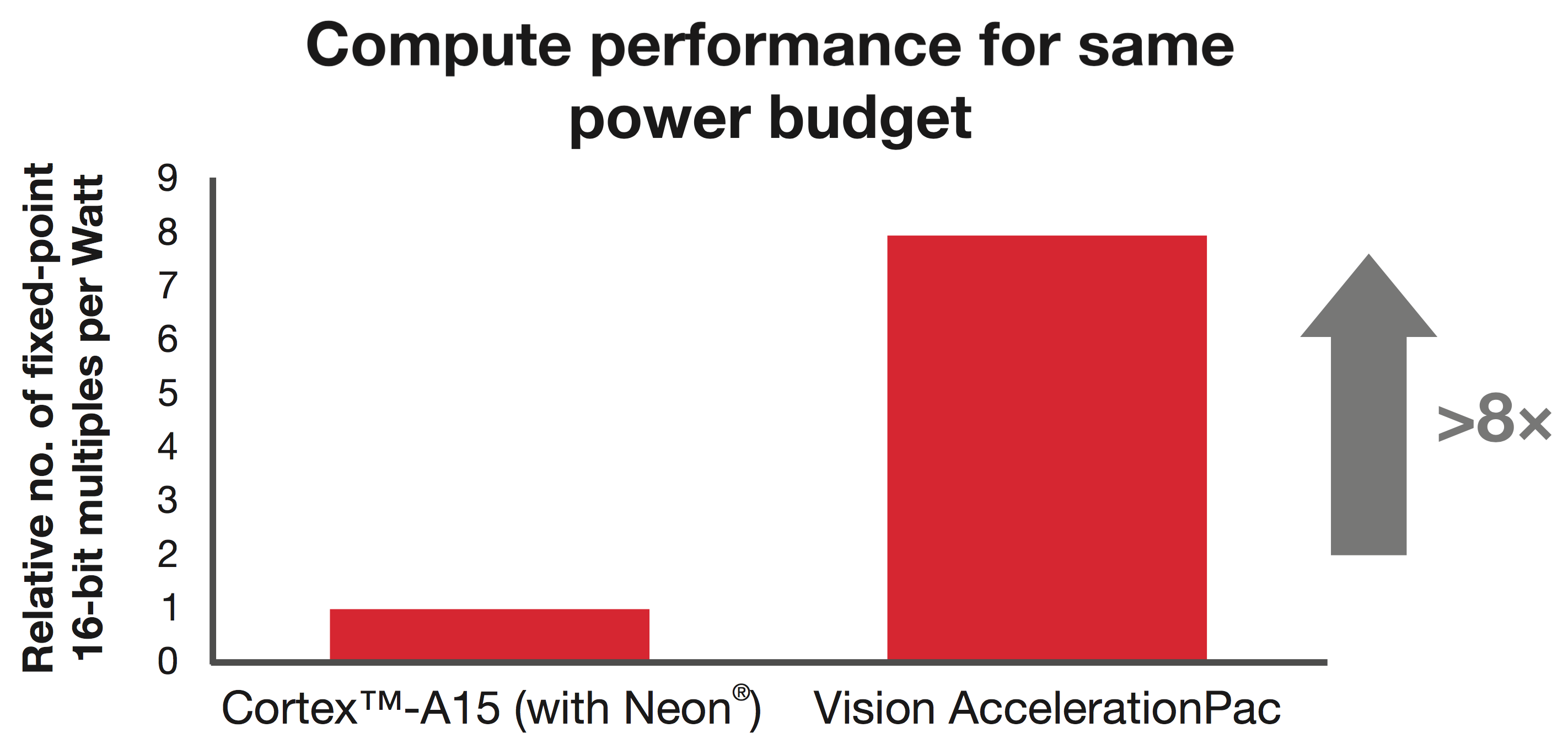
Figure 7: Vision AccelerationPac: >8× Compute performance for same power budget with respect to Cortex-A15
The TDA2x family includes multiple heterogeneous cores delivering the fastest and most efficient video / vision processing. It includes two latest-generation C66x fixed-/floating-point DSP cores that operate at up to 750 MHz to support high-level signal processing, as well as dual general-purpose 750-MHz ARM Cortex- A15 cores for control and general-purpose tasks. The dual ARM Cortex-M4 cores, each running at up to 200 MHz, are critical for system and peripheral control. The TDA2x SoC also includes TI’s IVA-HD technology which enables full HD video encode and decode, as well as dual SGX544 3D graphic cores capable of rendering 170 Mpoly/s at 500 MHz.
Lightning-fast processors and accelerators on TDA2x SoCs tightly coupled with large internal memories and a high throughput interconnect, deliver blazing compute performance and low latency critical for vision analytics processing. The TDA2x SoC has 2.5 MB of on-chip L3 RAM with Single Error Correct and Double Error Detect (SECDED) support to minimize impact of Soft Error Rate (SER). Each of the DSP cores has 32 KB of L1D data and 32KB L1P programming memory as well as 256 KB of L2 memory (L1 and L2 memory can be configured as either at memory or cache). The ARM Cortex-A15 core has 32 KB of L1 data and programming memory as well as a 2MB of L2 cache.
The TDA2x SoCs include a fully integrated set of peripherals. Each of three video ports interface to multiple video inputs (video port one and two can accommodate interface to four video inputs while a third video port is capable of connecting to two video inputs). The integrated high-performance GbE with AVB support is critical for low-latency streaming for Ethernet-based surround view systems. TI’s display subsystem is versatile with three video overlays, one graphic overlay and a write back path to memory. The TDA2x SoC’s external memory interface consists of two 32-bit wide DDR2/DDR3/DDR3L operating at 532 MHz. Two high-end DCAN controllers allow connection to the vehicle CAN bus without the need for a host microcontroller, reducing system cost and footprint. QSPIs and parallel NOR Flash interfaces deliver fast boot times critical for all ADAS applications. TI’s TDA2x SoC delivers an optimal mix of integration, performance and power efficiency with multiple flexible video input and output ports for LVDS- and Ethernet-based surround view systems.
The TDA2x SoC family provides a scalable architecture to meet the requirements of many applications in the ADAS space including front camera, surround view and sensor fusion. A scalable line of devices within the TDA2x family are available are available to meet the specific needs for these applications while enabling path to integration, reuse, lower cost and time-to-market (see Table 1).
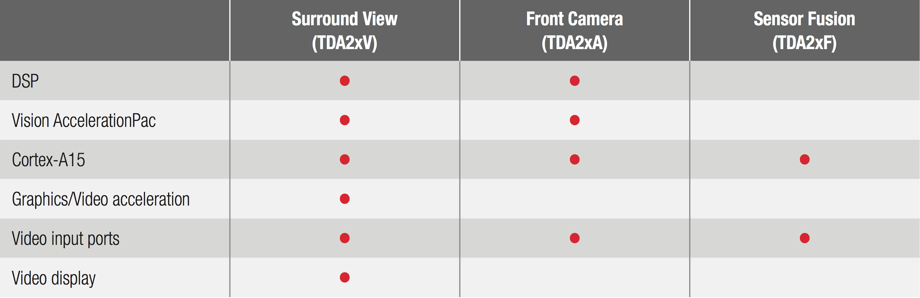
Table 1: TDA2x sub-families for Front Camera, Surround View and Sensor Fusion (typical configurations)
Functional safety and embedded security with TDA2x SoCs
As demand for functional safety systems increases, TI takes safety of its products seriously and provides SafeTI packages with documents and references customers can use to design their end systems for ASIL ratings.
TDA2x SoC is a Quality Managed device with the following salient hooks that can be used in context of functional safety enabling customers to design systems that meet ASIL levels.
- SECDED and parity protection in internal memories as well as SECDED-protected external memory interface
- Error detection in vector core and interrupt generation in Vision AccelerationPac
- Error handling, timeout and abort mechanism for safe interconnect bus implementation
- Illegal instruction aborts and traps on CPUs
- CLK routing features to implement clock monitoring
- Software-controlled voltage-monitoring options available on-chip
- Memory protection units, multiple MMUs and rewalls to implement freedom from interference
- Multiple clock and power domains to avoid common cause fails
- Software diagnostics-based approach to detect transient errors that may affect critical system configuration and computation
TDA2x SoCs come with a safety manual as well as detailed FMEDA for customers to assess their safety functions at granular implementation levels. TDA2x SoCs with the right features, diagnostic mechanisms and collateral enable seamless implementation of functional safety for customers to achieve ISO 26262 ASIL levels.
TDA2x software and tools – Building blocks for customer applications
TI’s Vision Software Development Kit (SDK) enables customers to rapidly prototype algorithms on the Vision AccelerationPac and DSP and to quickly and easily create different ADAS data flows involving video capture, video preprocessing, video analytics algorithms and video display. The Vision SDK is a multiprocessor software development platform for the TI family of ADAS SoCs. The SDK contains sample ADAS data flows which exercise different CPUs and hardware accelerators in the TDA2x SoC to show customers how to effectively use different subsystems. Use cases are well designed and realistic to help users understand the SDK design and can be used as a development starting point. The software showcases all the key performance indicators and instrumentation infrastructure that is supported by the design and has full platform enablement of all the IPs.
The AV BIOS/Vision SDK includes all tools and components necessary to build applications on TDA2x SoCs, including code gen tools, SYS/BIOS, IPC, OS-agnostic starterware, BSP drivers, networking and AVB stacks, codecs, block-based acceleration manager (BAM) and algorithm kernels. A BAM is at the core of the Vision AccelerationPac programming model and helps to maximize parallelism of the system. Within the Vision SDK, TI provides a well-designed vision framework with intuitive and consistent APIs for creating new and customizable system data flows as well as production-ready software, meaning the SDK framework can be used in the end production system. The Vision SDK framework and middleware provides buffer, DMA, data and control flow management across the SoC allowing customers to run multiple algorithms on DSP/Vision AcceleratorPac/Cortex-A15.
The Vision SDK addresses the need for low-power, low-latency and high-performance processing on embedded heterogeneous TDA2x processors, and helps ease the porting of existing image and vision algorithms developed on a PC to a TI embedded system.
TI also provides a number of libraries optimized to get full performance entitlement from the processor architecture. Using TI’s Vision SDK, customers can also write their own algorithms and quickly get to the field-testing phase.
TI offers a full range of tools to support the TDA2x SoC including Code Composer Studio™ Integrated Development Environment (CCStudio IDE) 5.4, ARM Code Generation Tools (CGT) 5.0.3, Cortex-A15 GCC, C6x CGT and EVE 1.0.0. This full suite of tools can be used to develop and debug embedded applications for the multiple cores on the TDA2x SoC. The tools include intuitive interfaces and take you through each step of development to get your system to market faster than ever before.
The TDA2x evaluation module (EVM) (see Figure 8) is available for evaluation and is designed to speed up development efforts and reduce time to market for ADAS applications. The main board integrates the key peripherals such as Ethernet, FPD-Link and HDMI, while the imager daughter board provides interfaces for popular imagers.
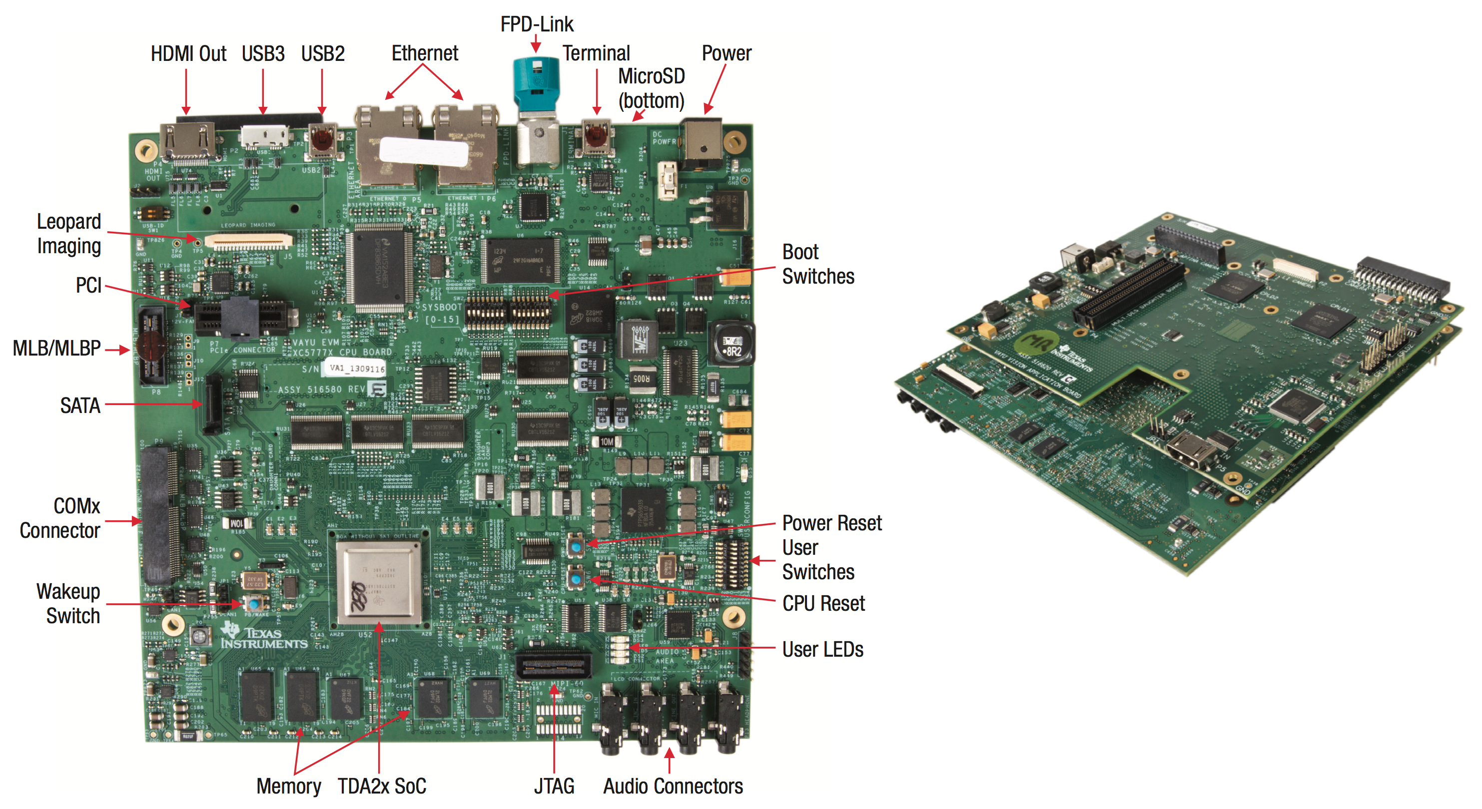
Figure 8: TDA2x Evaluation Module
Conclusion
The new TDA2x family of processors is another example of TI’s expertise and commitment to the ADAS market found in the more than 130 new TI automotive products. The TDA2x SoC is the best choice for highly integrated SoCs targeted at ADAS applications in large part to the cutting-edge, dedicated Vision AccelerationPac designed specifically for optimizing demanding vision capabilities in a system while reducing the overall power footprint. Customers can feel confident designing with the TDA2x SoC with the quality to meet ISO 26262 safety requirements. With TI, next-generation advanced driver assistance systems are now possible. Let TI’s new TDA2x SoC bring your new ADAS system to life with lightning-speed vision analytics.
For More Information
For additional information about the TDA2x family of SoCs, please visit www.ti.com/TDA2x.
References
- Google: The self-driving car logs more miles on new wheels
- Daimler aims to launch self-driving car by 2020
- Audi Demonstrates Its Self-Driving Car at CES 2013
- BMW Self-Driving Car
- Toyota Self-Driving Cars
Acknowledgement
The authors would like to thank Frank Forster, Stacie Ocnaschek and Aish Dubey for their contributions to this paper.
Zoran Nikolic
Lead Engineer for Advanced Driver Assistance, Texas Instruments
Gaurav Agarwal
ADAS Processor Marketing Manager, Texas Instruments
Brooke Williams
ADAS Processor Business Manager, Texas Instruments
Stephanie Pearson
Strategic Marketing Manager, Texas Instruments