Augmented reality can be found in smartphones, tablets, and PCs, in public displays, in head-up displays within various vehicles, in helmets for fighter pilots and first responders, in headsets and glasses, and possibly one day in contact lenses. Although broad in implementation and applications, these platforms share some common technologies, challenges, and opportunities. For example, they all have a display, one which needs to mitigate any vergence issues and must also have a wide field of view (FOV). Mobile devices also need to know where they are, a requirement which involves the implementation of simultaneous location and mapping (SLAM), and they all use at least one camera.
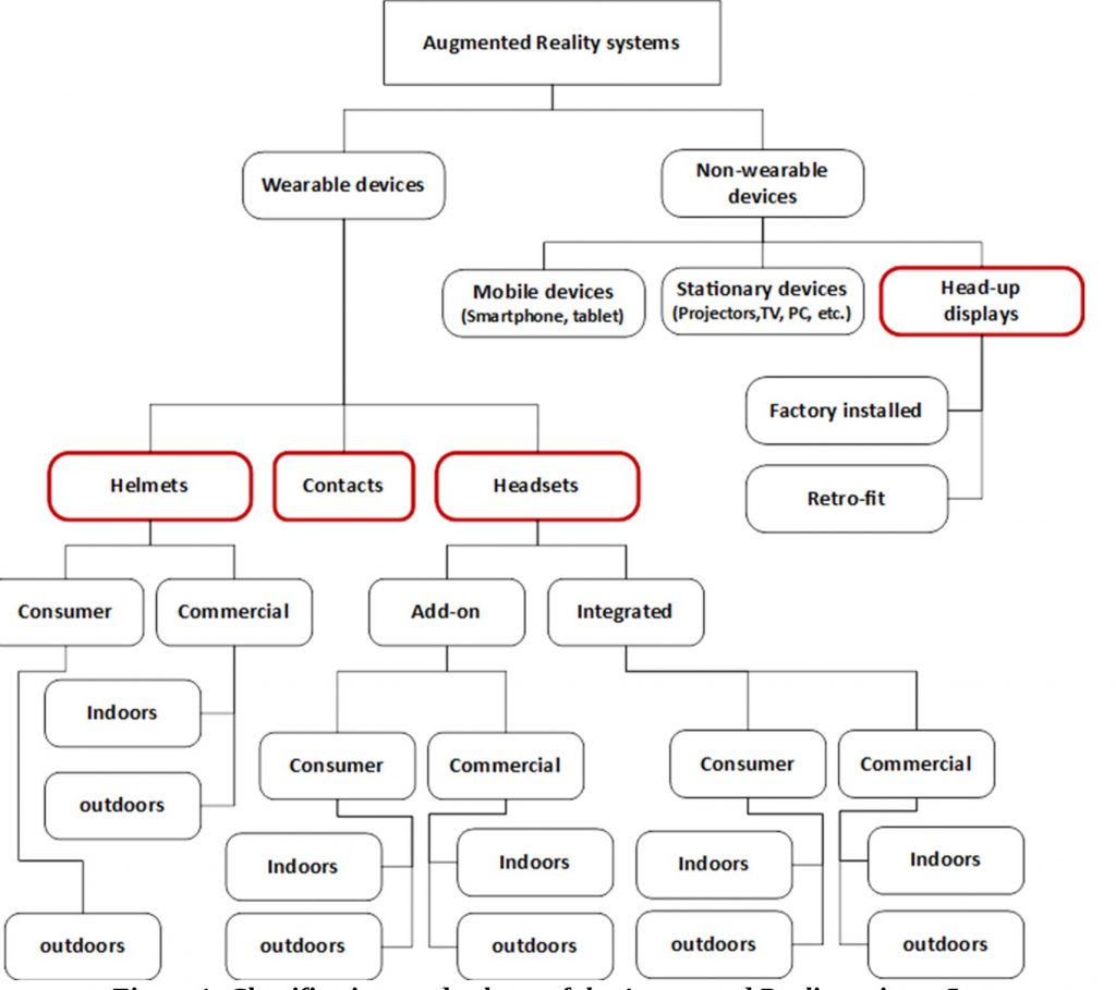
The term augmented reality (AR) encompasses a large and diverse topic, market, and set of technologies. Figure 1 shows the taxonomy of the AR space:

Figure 1. The classifications and subsets of the augmented reality universe reveal its diversity (courtesy Jon Peddie Research)
This article will look at the highly anticipated product category of wearable consumer-quality AR glasses, for indoor and outdoor use. Such things do not yet exist, but we are very close to seeing some limited-capability early versions. For this article they will generally be referred to simply as glasses.
Augmented reality superimposes computer-generated images over one’s normal field of view. A simple model to visualize the concept is to imagine you have a transparent screen fastened to the front of your glasses. It’s conceptually the same thing as using the forward-facing camera in a smartphone with a superimposed AR character like Pokémon.
Using a smartphone, which you can move to and from your eyes, allows you to get the vergence right so that the presentation looks correct.
Smart Glasses
As mentioned previously, I have subdivided smart-glasses suppliers and their products into two categories, integrated and add-on. Both of those categories are further subdivided regarding their ability or design to be used indoors and/or outdoors. Indoors is generally speaking an implied subset of outdoors, however there are some consumer smart-glasses that are integrated with sunglasses and would be inappropriate to wear indoors.
Integrated Smart Glasses
The distinction between an add-on augmented reality device and an integrated device may seem arbitrary. The distinction I’ve made, however, is that if the device can be attached to or worn with regular glasses, it’s an add-on device. Conversely, if it includes integrated lenses and other elements (such as a microphone, camera, or earphones) I consider it to be an example of integrated smart glasses, such as an augmented reality headset.
Indoors and Outdoors
I have further subdivided integrated smart glasses into consumer and commercial use cases, and each of those further into indoors and outdoors usage environments. These are important distinctions. Consider, for example, a sports headset like Intel’s Recon. For augmented reality glasses that support time-of-flight depth/distance measuring technologies, like Microsoft’s Hololens, the sensors depend on non-visible light that does not work well with UV outdoors (and can also be affected indoors by sunlight coming through windows). In other cases, the display may not be bright enough to overcome the ambient light from the outside.
Consumer
Smart glasses can vary widely in design, such as the newer consumer spectacles offered by companies like GlassUp’s UNO, Laforge’s Shima, and Ice’s Theia (Figure 2). These devices have a small on-board real-time O/S and communicate via Bluetooth Low Energy (BTLE) with a smartphone or tablet computer running either Android or iOS. They display to the user any kind of message that the smartphone has already elaborated, and they also leverage the smartphone’s GPS, gyro, accelerometer, and other sensors.

Figure 2. Laforge’s augmented reality eyewear delivers a “normal” look (courtesy Laforge).
Consumer smart glasses are mobile battery-powered devices, and look close to (if not identical to) regular glasses. Some consumer versions of smart glasses also include a small box or package, typically the size of a smartphone, connected by them by a thin cable. The box is worn on the belt or placed in a pocket.
Included in the consumer category are smart glasses designed for specific functions such as sports and exercise, with examples being Intel’s Recon and Kopin’s Solos. I do not include Google Glass or its imitators in the consumer category, since they are conspicuous in design, calling attention to themselves and the wearer, which is just the opposite of what the average consumer would desire to wear in public.
Vergence
Prolonged use of conventional stereo displays can cause viewer discomfort and fatigue because of the vergence accommodation. (Vergence is the simultaneous movement of both eyes in opposite directions to obtain or maintain single binocular vision.) Visual fatigue and discomfort occur as the viewer attempts to adjust vergence and accommodation appropriately (Figure 3).
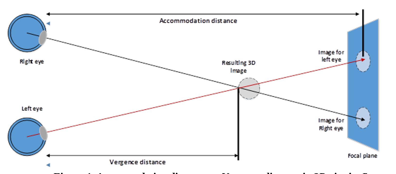
Figure 3. Accommodation distance versus vergence distance in 3D viewing can result in viewer discomfort and fatigue (courtesy Jon Peddie Research).
In a conventional 3D stereo projection, one’s brain can get confused between the overlapping projected view and the viewer’s natural focus at his or her focal plane, creating conflicting depth cues. Your eye convergence is at the intersection of the view paths (the vergence distance), but the brain is tricked into seeing it in the distance (the accommodation distance), which creates the vergence accommodation conflict. The result of this discrepency quickly becomes intolerable for close images. It is aggravated even more if the viewer tries to “touch” the virtual 3D objects, because the viewer’s eye focuses on his or her hand, which makes the distant virtual image blur and become confusing. The result is that the illusion of 3D is lost, and the viewer experiences discomfort.
Field of View
The field of view (FoV) (FoV) of an augmented reality device is one of the most important and controversial aspects of the device. The calculation of field of view is basic trigonometry, with the subtended angle derived from the horizontal distance to the focal plane and the vertical distance covered (seen), as illustrated in Figure 4.
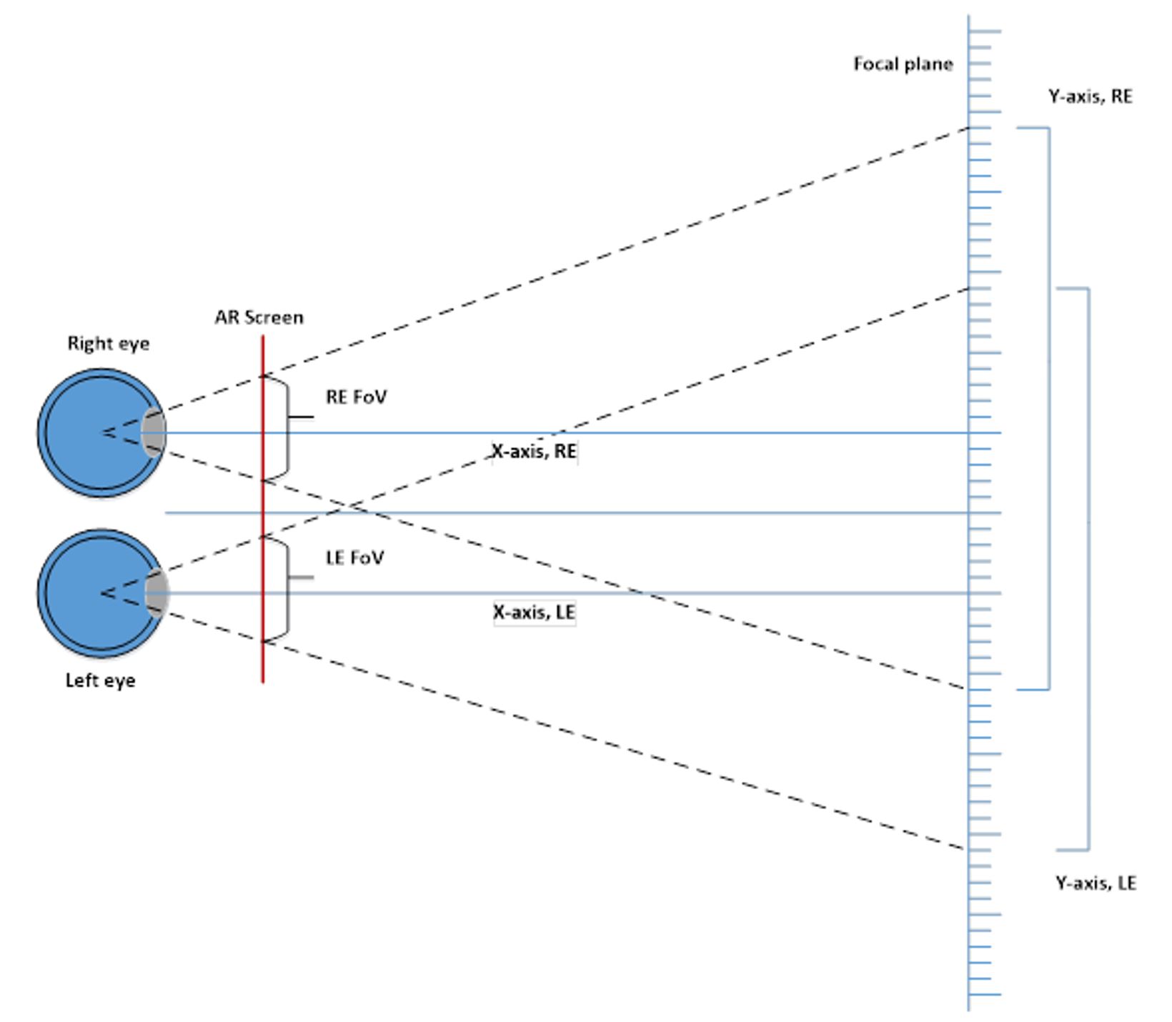
Figure 4. The determination of field of view involves basic trigonometry calculations (courtesy Jon Peddie Research).
However, outside the laboratory and in the real world, field of view can sometimes be difficult to judge. In principle, to measure the augmented reality field of view, one holds a ruler at a known distance from one’s eyes and then marks down where the apparent left and right edges of the display area fall on the object. Knowing the distance X between the left/right markers and the distance Y between the eyes and the object, the FoV is calculated via the equation FoV = 2×tan-1(X / (Y×2)).
Some people mistakenly believe that a small FoV is the result of either the augmented reality device’s limited graphics processing power or a limited pixel count display, and is therefore easily improved with a more powerful GPU and/or higher resolution display. The reasoning behind this belief is that increasing the field of view of a 3D graphics application leads to a proportional increase in the number of pixels displayed, and therefore the GPU has to do more processing and the display has to contain more pixels. In the case of games, without explicit frustum culling, that would be a correct conclusion. However, with modern GPU programs that can cull complex geometric objects automatically, the effect is usually small as long as the final rendered image size in pixels stays the same.
Displays
Displays are our main source for information and, often, interaction. Augmented reality and associated technologies are delivered to the user through a display or projection device of some type, and at some distance. It can be/is different for all cases.
Proximity
Displays can be in three different locations: far (signage, billboards, annunciators, command and control, conference rooms, CAVEs (Cave Automatic Virtual Environments, consisting of a cube-shaped room in which the walls are rear-projection screens1), etc.), near (computers, in-vehicle dashboard/cockpit, TV, etc.), and close (wearables – e.g., head-mounted displays, watches, etc.). Near-displays are sub-divided into lean-back and lean-forward. TV viewing is an example of lean-back, while computer viewing exemplifies lean-forward. Cockpit and in-vehicle displays are also lean-forward, because like a computer they typically involve some form of interactivity.
Close
Close displays are sub-divided into four primary categories: virtual reality (VR) head-mounted displays (HMDs), augmented-reality displays (helmets and glasses), handheld devices such as smartphones and tablets, and personal media players (PMP) and devices (PMD) primarily for entertainment (although they can also be used for business). A fifth coming-eventually-manybe category could be contact lenses and implants.
Augmented Reality
Likewise, augmented reality-head-mounted displays, which are close HMDs, are sub-divided into data and graphics categories. Data augmented reality head-mounted displays are those devices that only deliver information in the form of elementary data (i.e., text and very primitive graphics objects such as a box or triangle). Graphics augmented reality-head-mounted displays deliver complex computer-generated graphics data, such as engineering drawings, maps, or entertainment.
Augmented reality-head-mounted displays come in the form of helmets (which can be data-only or graphics-capable) and glasses (also known as smart glasses). Augmented reality can also be delivered to tablets and smartphones that have forward-facing cameras. When augmented reality is used on such handheld devices (which could include notebook computers), they are sometimes referred to as see-through or “Windows on the World” (WOW) systems.
Traditional user interfaces (UIs) for “off-the-desktop” applications display the digital information on flat 2D surfaces. Spatially augmented reality (SAR) uses projectors to display on walls, for example, or a table top that a user can interact with without need for a head-mounted display or handheld device. It is like a CAVE but lacks the physical 3D aspect of a CAVE.
Color Depth
The number of colors producible by the display, known as the color depth, is of variable importance to the viewer depending on the type of data being displayed. The human eye can discriminate up to ten million colors. However, if only text or simple maps are being displayed, the image generator used does not need to provide a wide color depth. On the other hand, if complex images of mechanical devices or human anatomy are being displayed, for example, a wide color depth is critical for discrimination.
Refresh Rate
Also known as frame rate, the refresh rate is the frequency at which an image generator produces consecutive images to the display and is measured in frames per second (FPS). A frequency lower than about 20 FPS is perceived as flicker; below 12 fps the frames are considered separate images to the individual. Faster rates, on the other hand, create the illusion of motion. 24 fps is the current minimum video standard which would be the expectation for HMD display refresh, however, as explained in more detail elsewhere in this article, to avoid latency the refresh rate may be as high as 120 fps. Frame rate is also expressed as Hz in some cases.
Twenty-four frames per second (or more) is used for movies. Film projectors use a double gate and display the same frame twice to get the flicker rate up to 48 Hz. Flicker is more of an issue when there is blanking (no image) between frames, such as with film or a CRT that have blanking at or below 60hz. Today’s displays generally update from 60 to 120 Hz. Going to higher frame rates reduces any perceived jitter with fast-moving images.
Display issues
The virtual reality and augmented reality/mixed reality head display markets use very different display technologies. The virtual reality market typically uses large flat panels which are less expensive and make it easy to support very wide FOV, albeit with greater than 4 arcmin per pixel angular resolution. The augmented reality/mixed reality “see-through” markets, with the notable exception of the large Meta 2, for example, use microdisplays (DLP, LCoS, OLED).
The most common display technologies used in augmented reality are LCD, OLED flat panel on glass, OLED microdisplays on silicon, DMD (digital micromirror device, an optical semiconductor on which DLP technology is based), LCoS, and micro LEDs. Larger flat panel (LCD and OLED) displays have been sold to augmented reality headset developers as stand-alone modules, and in some cases, use industry standard interfaces such as DVI, HDMI, or DisplayPort. The microdisplays (LCoS, DLP, OLED) are generally sold as chipsets with controllers that support various inputs.
While these interfaces allow for easy interconnections, they impose certain restrictions that are difficult to work around. Specifically, they deliver display data sequentially, a technique derived from the raster scan method (developed in the late 1930s for cathode ray tube (CRT) television sets). The sequential approach introduces nearly an entire video frame of latency in the display device itself; even worse in the case of field sequential color. The processing algorithms for DLP’s sometimes trade some loss of image quality for lower latency, but even so the latency is more due to field sequential color. Since the display interface is raster-scan-based, a display device must receive an entire image before it can start to display a single pixel of that image.
Field sequential color is at a huge disadvantage in terms of latency. DLP compounds this with the dithering and other additional processing needed, all of which takes time. FSC LCoS is better in terms of latency but it still has to wait for a frame to be totally received before it can display its first color. And on devices that accept scan-line data, the display of the bottom of the image occurs much later than the display of the top of the image. Therefore, raster scan is inherently unsuited for low-latency applications, unless the output of the scan to the display is performed at very high rates, an approach which can create memory access and power consumption issues.2
Head-worn (headset or helmet) augmented reality systems optically combine the computer-generated image with the user’s direct view of the surroundings (known as “optical see-through”). This approach contrasts with that used in smartphone and tablet-based augmented reality applications, which combine the computer-generated image with video imagery from the device’s camera (known as “video see-through”). For head-worn displays, optical see-through with its direct no-latency view of the viewer’s local environment is desirable and likely indispensable for extended use.
However, optical see-through comes with an ineherent problem. Any optical technology that combines a computer image with the real world is going to have at least some degratory effect on the real-world view. At a minimum, it is going to dim the real world, and this muting can be made even worse as the real world passes through the optical structures that direct the computer-generated image toward the eye. Unlike video see-through displays, which allow synchronization of real and processor generated (virtual) images by deliberately delaying the video stream, optical see-through augmented reality must present synthetic imagery at the speed of “reality” to keep virtual and real objects aligned. Therefore, it must rely on minimal latency or on prediction techniques when computing synthetic imagery.3
Unfortunately, latency effects accumulate through all stages in the video pipeline of an augmented reality system (tracking, application, image generation, and scanned output to the display), so if special techniques are not employed (e.g., minimizing latency or predictive techniques) the debilitating effects of an optical see-through approach multiply. However, in the worst case, predictive techniques do the opposite of what they should do if the motion changes direction. Not only the magnitude of the offset between the intended and the achieved location of the computer-generated object is a factor, but also the change in the offset as a function of time – the synthetic object appearing to wander or swim about the real scene.4 While predictive tracking can significantly reduce the misalignment between synthetic and real imagery, errors are still present, especially during rapid changes in head pose.
Direct addressing of the display by the image generation section of the augmented reality system is possible with matrix-like devices such as OLED, LCD, microLED, LCoS, DMD and, laser-beam scanning (LBS). Pico projectors which use a LCoS chip are assembled subassemblies which take serial data and therefore, are inherently latent. As augmented reality systems develop, the developers of such systems have to get deeper into the display technology and drive it directly. Here the industry encounters the classic chicken-and-egg problem. Until augmented reality system builders have sufficient volume of sales, the cost of displays with the necessary exposure of their construction will be high because they will be treated as special class devices. That will keep the cost (therefore price) of augmented reality head-worn systems high, which will keep the sales volume down.
Eye-box
The eye-box is the volume of space within which an effectively viewable image is formed by a lens system or visual display, representing a combination of exit pupil size and eye relief distance. The term was first used by John Flamsteed (1646–1719), an astronomer in the late 17th century.
The eye-box is often equivalent to the exit pupil (a virtual aperture in the optical system) and consists of the range of eye positions, at the eye relief distance (distance between the vertex of the last optic and the exit pupil), from which the entire image produced by the display is visible. This includes both angular and lateral movement of the eye. The exit pupil is important because only the light rays which pass through the virtual aperture can exit the system and enter the wearer’s eyes
The eye-box is also shared with the FoV (Figure 4). The effective eye-box of a smart glass can be much larger than the real optical eye-box; various mechanical adjustments of the combiner may be used to match the exit pupil of the combiner to the entrance pupil of the user’s eye. However, for any position of the combiner, the eye box has to allow the entire FoV to be seen unaltered, at the target eye relief. It may happen that for a specific position of the combiner, the entire display might be seen indoors (large pupil), hut the edges of the display might become blurry outside due to the fact that the eye pupil diameter decreases.5
Augmented Reality Displays
The first augmented reality display was the teleprompter developed by Hubert Schiafly in 1950 and based on the concept of Pepper’s Ghost6. The first wearable augmented reality device was the Philco head-mounted remote surveillance system developed in the early 1960s7. The portable display used in augmented reality devices has been a challenge and often the limiting component (due to size, weight, cost, power consumption, heat, brightness, resolution, reliability and durability) for a wearable device. As a result, multiple solutions have been developed, offered, and tried, and we have learned that there is no panacea, no “one size fits all.”
This section will discuss wearable augmented reality device displays, not the displays found in mobile devices such as smartphones, notebooks, tablets, and HUDs. Those devices are capable of providing an augmented reality experience, they just aren’t (easily) wearable. Also, most augmented reality headsets (helmets, glasses, add-ons, etc.) only employ one display (usually over the right eye). When two displays are used, the challenge of generating a projected stereo 3D (S3D) image is added to the workload of the image generator and content; this is one of the reasons single displays are the primary model.
This design choice doesn’t mean you can’t view 3D objects with an augmented reality headset, it just means the objects will be flat. However, because the object will be effectively stationary, you can move around it and get the effect of stereo. Stereoscopic viewing is one of the distinctions between augmented and virtual reality. Virtual reality headsets present two separate views to create the pseudo stereoscopic image (using two flat displays) and your brain creates the three-dimensional image. Mixed reality headsets, which are basically virtual reality headsets with a forward-looking camera, also generate a quasi-stereoscopic 3D image.
Work on lightweight display devices and schemes for using them will go on for some time, perhaps until we have implants such as those developed at Monash University in Clayton, Victoria’s work8 or the Alpha IMS developed by University of Tübingen, Germany.9 In the meantime, other developments exist, ranging from adaptation of organic light-emitting diode (OLED) screens produced for smartphones to experimental contact lens. Display technologies are quite complex, and volumes have been written about them. It is beyond the scope of this article to replace, compete, or even approach those tomes. Obviously, we couldn’t experience augmented reality without a display device of some type, and as is so often the case, no one solution can (or will) satisfy all requirements.
Augmented reality is the next, major, mobile computing platform, and everything we’ve learned from smartphones will be used for augmented reality. That will include how to squeeze incredible performance out of processors while using minimal power which lets the weight be reduced. The mass production of smartphones drove down the price of sensors and display screens, and augmented reality device builders are benefiting from this (Figure 5). Scientists have a lot to work to do given the capabilities of human vision. In some cases, our vision is good enough to make accommodation for slower displays and a certain amount of latency. And, on the other hand, the increasing power of processors will also enable sharper images integrated into reality, easier to read text, and richer colors. When improvements come, our eyes are ready for it.
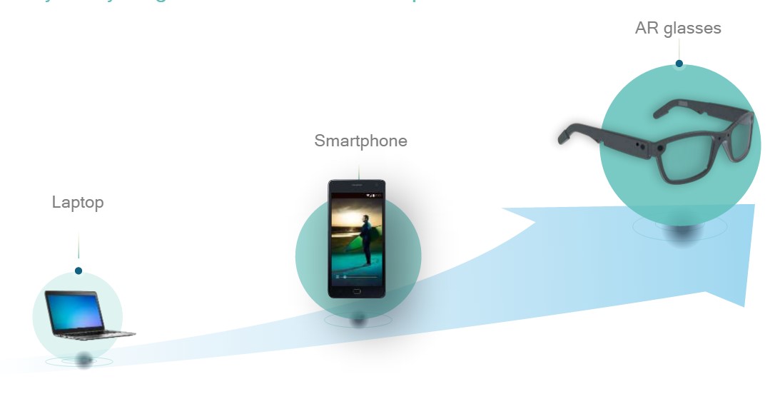
Figure 5. Smartphone technology will enable the development of consumer and commercial augmented reality devices (courtesy Qualcomm).
At the same time, Moore’s Law has continued to enable semiconductors to get smaller, denser, and more powerful. Semiconductor manufacturing of screens such as OLEDs and microLEDs has also benefited augmented reality. And whereas some people think the consumer version of augmented reality, when it arrives, will replace the need for a smartphone, augmented reality will forever be in the debt of the smartphone industry. Like smartphones, the augmented reality evolution will take years but has the potential to be huge. My personal forecast/hope is that by 2020-2025 we will use augmented reality as casually and commonly as we do a smartphone today. And some people have predicted it’s only a matter of time before we trade in our smartphones for smart glasses.
Cameras
In order for augmented reality to work in all systems (with the possible exception of in-vehicle head-up displays), one or multiple cameras needs to be present to see what the user is seeing. Cameras vary in resolution, speed, color depth, size, weight, and other characteristics. No single dominant augmented reality camera sensor approach exists. Some systems have two forward-looking cameras to provide stereoscopic depth sensing. Other systems have multi-spectral cameras to sense IR and/or UV. The cameras can also be used for recording.
An augmented reality’s forward-facing camera can be used for image recognition to enable the device to identify an image in the real world based on its unique visual features. Image recognition is used to identify what has caught the user’s attention so information about it can be displayed. More advanced augmented reality devices will use advanced computer vision techniques as part of an artificial intelligence (AI) system. The goal of computer vision is for computers to achieve human-level understanding of images. Augmented reality is pushing the boundaries of computer vision and trying to achieve this goal with computer vision and related technologies.
Depth Sensing
Depth sensing and other 3D imaging techniques also use cameras. Depth sensing can be accomplished by photogrammetric stereo triangulation, or by emitting an IR or UV pulse and timing how long it takes to be reflected (a time-of-flight technique akin to RADAR), or by emitting a special pattern known as structured light. Once again, no single solution will serve all applications.
Using structured light a 3D camera has a projector that sends out an infrared dot pattern to illuminate the contours of the environment. This is known as a point cloud. As the dots of light get further away from the projector they become larger. The size of all the dots are measured by a camera algorithm and the varying sizes of the dots indicates their relative distance from the user.
Thin Photo Sensors and Lenses Translate Into Slender, Lightweight Devices
Using a graphene sheet nanometers thick, South Korea’s Institute for Basic Science (IBS) has developed the world’s thinnest photodetector. Graphene is conductive, and thin (just one-atom thick), transparent, and flexible. However, it doesn’t behave like a semiconductor, so its application in the electronics industry has limited use. To increase its usability, IBS researchers sandwiched a layer of the 2D semiconductor molybdenum disulfide (MoS2) between two graphene sheets and put it over a silicon base. With a thickness of just 1.3 nm, 10 times smaller than standard silicon photodiodes, this device could be used in wearable electronics (i.e., AR), smart devices, Internet of Things (IoT), and photo electronics (Figure 6).
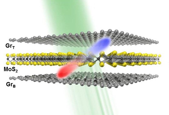
Figure 6. Device with the MoS2 layer sandwiched between top (GrT) and bottom (GrB) graphene layers. Light (green ray) is absorbed and converted into an electric current. When light is absorbed by the device, electrons (blue) jump into a higher energy state and holes (red) are generated in the MoS2 layer. The movement of holes and electrons created by the difference in electronic potential (courtesy IBS).
The IBS researchers initially thought the device would be too thin to generate an electric current, but unexpectedly, it worked. “A device with one-layer of MoS2 is too thin to generate a conventional p-n junction, where positive (p) charges and negative (n) charges are separated and can create an internal electric field. However, when we shone light on it, we observed high photocurrent. It was surprising! Since it cannot be a classical p-n junction, we thought to investigate it further,” explains Yu Woo Jong.10
To understand what they found, the researchers compared devices with one and seven layers of MoS2 and tested how well they behave as a photodetector, that is, how they are able to convert light into an electric current. The researchers found that the device with one-layer MoS2 absorbs less light than the device with seven layers, but it has higher photoresponsivity. “Usually the photocurrent is proportional to the photo absorbance, that is, if the device absorbs more light, it should generate more electricity, but in this case, even if the one-layer MoS2 device has smaller absorbance than the seven-layer MoS2, it produces seven times more photocurrent,” said Yu.
Why is the thinner device working better than the thicker one? The research team proposed a mechanism to explain why this is the case. They recognized that the photocurrent generation could not be explained with classical electromagnetism, but could be with quantum physics. When light hits the device, some electrons from the MoS2 layer jump into an excited state and their flow through the device produces an electric current. However, in order to pass the boundary between MoS2 and graphene, the electrons need to overcome an energy barrier (via quantum tunneling), and this is where the one-layer MoS2 device has an advantage over the thicker one. Because the device is transparent, flexible, and requires less power than the current 3D silicon semiconductors, it could accelerate the development of 2D photoelectric devices, say the researchers.
Thin Sensors Need Equally Thin Lenses
The world’s thinnest lens, one two-thousandth the thickness of a human hair, is opening the door to flexible computer displays and a revolution in miniature cameras. A group of researchers from the Australian National University (Canberra) and the University of Wisconsin (Madison) have discovered that a single molecular layer L of molybdenum disulfide (MoS2) has a giant optical path length, about 10 times greater than to another monolayer material, graphene. Although this may seem like an esoteric result, it has a very practical consequence for photonics. As the researchers have demonstrated, just a few monolayers of MoS2 can be used to create what the researchers call the “world’s thinnest optical lens,” only 6.3 nm thick. With a diameter of about 20 μm, the concave MoS2 lens the researchers fabricated has a calculated focal length of −248 μm at a 535-nm wavelength.
Lead researcher Dr Yuerui (Larry) Lu from The Australian National University (ANU) has said the discovery hinged on the remarkable potential of the molybdenum disulphide crystal. “This type of material is the perfect candidate for future flexible displays,” said Dr Lu, leader of the Nano-Electro-Mechanical Systems Laboratory in the ANU Research School of Engineering. “We will also be able to use arrays of micro lenses to mimic the compound eyes of insects,” he noted. “Molybdenum disulphide is an amazing crystal,” said Dr Lu. “It survives at high temperatures, is a lubricant, a good semiconductor and can emit photons too.” He forecasts, “the capability of manipulating the flow of light in atomic scale opens an exciting avenue towards unprecedented miniaturization of optical components and the integration of advanced optical functionalities.”
Molybdenum disulphide is in a class of materials known as chalcogenide glasses that have flexible electronic characteristics that have made them popular for high-technology components. Dr Lu’s team created their lens from a crystal 6.3-nanometres thick – 9 atomic layers – which they had peeled off a larger piece of molybdenum disulphide with sticky tape. They then created a 10-micron radius lens, using a focused ion beam to shave off the layers atom by atom, until they had the dome shape of the lens. The team discovered that single layers of molybdenum disulphide, 0.7 nanometers thick, had remarkable optical properties, appearing to a light beam to be 50 times thicker, at 38 nanometers. This property, known as optical path length, determines the phase of the light and governs interference and diffraction of light as it propagates.
“At the beginning, we couldn’t imagine why molybdenum disulphide had such surprising properties,” said Dr Lu. Collaborator Assistant Professor Zongfu Yu at the University of Wisconsin, Madison, developed a simulation and showed that light was bouncing back and forth many times inside the high refractive index crystal layers before passing through. Molybdenum disulphide crystal’s refractive index, the property that quantifies the strength of a material’s effect on light, has a high value of 5.5. For comparison, diamond, whose high refractive index causes its sparkle, is only 2.4, and water’s refractive index is 1.3.
Localization, Tracking, and Navigation Sensors
Knowing where you, from both the standpoints of location and orientation, is is one of the most critical functions in augmented reality. How can a system identify things and deliver potentially mission critical information in a timely manner if it doesn’t know where you are? But how does it know where you are? Just as a smartphone (which as previously noted can also be an augmented reality device) “knows” where you, so can a dedicated augmented reality device (whether standalone or smartphone-tethered). Methods include GPS radios, triangulation with cell phone towers, accelerometers, compasses using magnetometers, and complex combinations of multiple of these. In mission-critical cases such as military helmets, the location data comes from the complex and redundant sensors and radios in the airplane, ship, or tank.
Precision positioning requires accurate initial location fixes, followed by high-resolution incremental measurements until the next accurate fix can be obtained. SLAM, for example, provides a stable measurement but suffers from introduced error accumulation and scale ambiguity that results in less accurate localization over time. One concept to overcome that is to include constraints provided by a pre-defined 3D model of an object of interest (i.e., where the user is, in a general sense) a priori knowledge (e.g. model-based tracking). Such an approach results in a very accurate and stable localization. Referred to as a model-based solution, the approach relies on a prebuilt map of 3D features. The combination of position and orientation is referred to as the pose of an object, even though this concept is sometimes used only to describe the orientation. The pose of the camera is estimated on-line by matching 2D features extracted from the images with the 3D features of the map.
Summary and conclusion
AR encompasses a large and diverse topic, market, and set of technologies, and can be found in smartphones, tablets, and PCs, in public displays, in head-up displays within various vehicles, in helmets for fighter pilots and first responders, in headsets and glasses, and possibly one day in contact lenses.
AR glasses share some common technologies, challenges, and opportunities with all the other implementations of AR, but glasses are particularly challenging. For one thing, they have to include a lightweight, low-power, adjustable-brightness display that can be used during the day in bright sunlight, or well-lit offices, and in the evening on dark streets. The display has to mitigate any vergence issues and must have a wide field of view. AR glasses also have to know where they are, a goal which often involves SLAM, and they all use at least one camera. All of that hardware and associated software is really too much to cram into a set of spectacles that one would be willing to wear in public, at least for now, so the first two or three generations will probably be used in conjunction with a smart-phone, making the glasses a terminal for the phone.
When we have such glasses and they are widely adopted, our lives will be different, better, and most importantly safer. With a camera recording everything we see and do, there will be no more debates about who did or said what; we will all be honest witnesses. We will never be lost, and we won’t have to be afraid to speak to strangers in a foreign land (or, for that matter, our own land). We will never accidentally wander down an unsafe street, and thanks to IR sensors we’ll also be able to see in the dark. People hard of hearing will have subtitles in view all the time.
We all wear glasses now, some with corrective lenses, others for protection from the sun. The future AR glasses will be no more obnoxious than that. We’ll all be experts, and safe.
By Jon Peddie
President and Founder, Jon Peddie Research
References
- https://en.wikipedia.org/wiki/Cave_automatic_virtual_environment
- Zheng, Feng., Whitted, Turner., Lastra, Anselmo., Lincoln, Peter., State, Andrei., Maimonek, Andrew., and Fuchs, Henry., Minimizing Latency for Augmented Reality Displays: Frames Considered Harmful, IEEE International Symposium on Mixed and Augmented Reality 2014, p.195
- Rolland, J. P., and Fuchs, H., Optical Versus Video See-Through Head Mounted Displays. In Presence: Teleoperators and Virtual Environments, pages 287–309, 2000.
- R. L. Holloway. Registration Error Analysis for Augmented Reality. Presence, 6(4):413–432, 1997.
- Fundamentals of Wearable Computers and Augmented Reality, Second Edition, edited by Woodrow Barfield, CRC Press, Taylor & Francis Group, Boca Raton, FL 2016
- https://en.wikipedia.org/wiki/Pepper%27s_ghost
- Comeau, C. P. and Bryan, J. S., 1961, Headsight television system provides remote surveillance, Electronics, 10 November, 34, 86-90.
- Bionic eye will send images direct to the brain to restore sight, New Scientist, https://www.newscientist.com/article/mg22830521-700-bionic-eye-will-send-images-direct-to-the-brain-to-restore-sight/
- Eberhart Zrenner; et al. (2010). Subretinal electronic chips allow blind patients to read letters and combine them to words,. Proceedings of the Royal Society B. doi:10.1098/rspb.2010.1747.
- Unusually efficient photocurrent extraction in monolayer van der Waals heterostructure by tunneling through discretized barriers, Woo Jong Yu et al, Nature Communications (2016); DOI: 10.1038/ncomms13278