By Tina Jeffrey
Program Manager
CogniVue
This is a reprint of a CogniVue-published white paper in the company's Knowledge Center, and is also available here (1.2 MB PDF).
The CogniVue Smart Enhanced BackUp Camera (SmartEBC) is a revolutionary automotive rear-view camera application that analyzes image data from a single image sensor to track objects in the scene, and perform feature detection and distance estimation of the nearest obstacle to the rear of the vehicle. SmartEBC executes on CogniVue’s CV220X family of SoC devices utilizing its patented APEX parallel processing technology. SmartEBC augments the functionality of traditional backup camera products with the ability to algorithmically interpret the scene by detecting objects behind a vehicle when in reverse, and alert the driver with critical real-time information to avoid a collision.
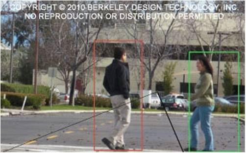
Traditional backup cameras provide a simple, distorted view of the rear environment to the driver. The driver must scan the environment for obstacles in the rear path while performing a vehicle reversing operation without an aid. CogniVue’s SmartEBC application detects and recognizes the closest obstacle at the rear of the vehicle including moving objects such as pedestrians and cyclists. For scenarios in which a collision is imminent such as the vehicle is moving towards an object or an object is moving towards the vehicle, an alarm signals the presence of the obstacle to the driver so that appropriate braking time is accommodated. Distance calculations are performed continuously when a vehicle is in motion moving towards a stationary object, for the purpose of providing the driver with obstacle ‘zone’ alarms (green, yellow, red) which represent varying distances between the detected object and the vehicle.
SmartEBC Offers Multiple Viewing Modes
SmartEBC software supports three distinct driver-selectable views of the rear vehicle environment. These views are described below, with illustrations of each that follow.
Full view provides an undistorted wide-angle view of the rear environment; Full view is the default view. It corrects the “fish-eye” or wide-angle lens distortion and renders the images to the display for the driver. The figure below illustrates the effects of dewarping/perspective correction when the system operates in Full view mode.
Top view, also referred to as “Bird’s-Eye view” provides an undistorted view of the rear environment from the vantage point of looking down from above.
Left/Right view, also referred to as “Split view” provides undistorted views of the far left and right regions of the rear environment of the vehicle.
Distorted "Fish-Eye" Input Image (above left), Corrected "Full View” (above right)
Full View (above left), – Top View (above right)
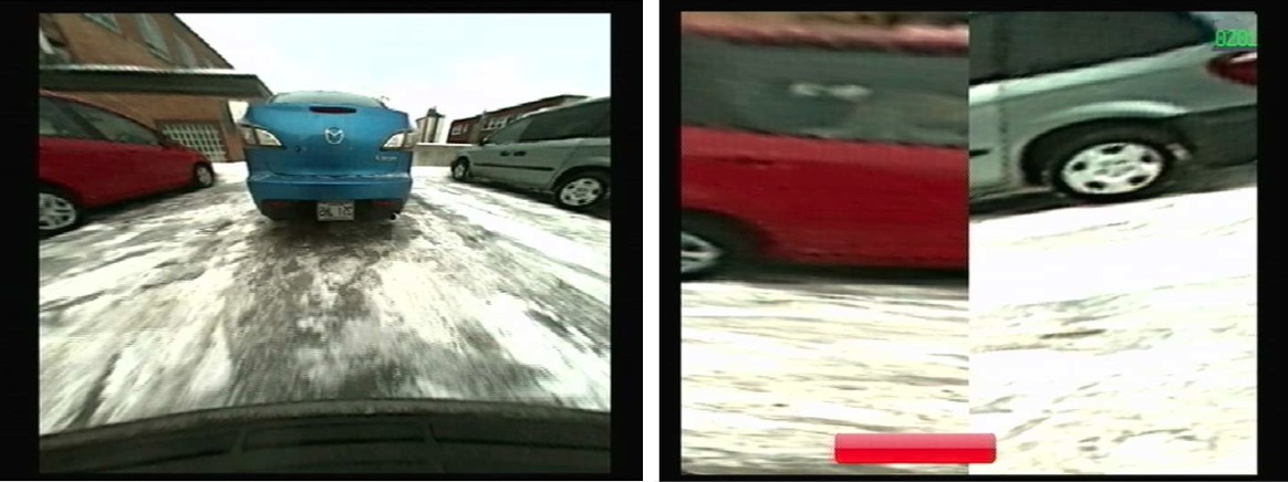
Full View (above left) – Left/Right Split View(above right)
A single button on a camera module product interfaces to a General Purpose I/O to allow the user to toggle between the multiple views. Through a similar mechanism, the product may offer a feature for programming a customized viewing mode sequence for the system, different from the default ordering if desired. The CV220X has numerous GPIOs available to system integrators to accommodate a variety of system designs.
SmartEBC Algorithm: Vision Based Obstacle Detection and Distance Estimation
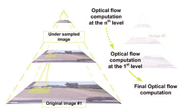
The SmartEBC algorithm detects objects through 3D reconstruction of the scene using a single rear view parking camera by first dewarping the incoming raw video frames and then performing the necessary transformations on the image scene. Image features across multiple frames are detected and tracked using optimized versions of Good Features To Track (GFFT) and Block Matching algorithms. An image feature in the context of SmartEBC is either a corner or a speckle found within a small patch of the image, and is detected by analyzing these patches for strong gradients occurring in at least two different directions. SmartEBC detects and tracks features both on the ground to estimate the vehicle’s motion, and features associated with obstacles in the scene. For the SmartEBC to accurately calculate the ground motion a minimum vehicle speed of 3 cm/s is required (~0.1 km/hr). The algorithm is optimized to reduce false detections prior to reporting the distance of the nearest obstacle to the driver.
The figure below shows the regions of interest associated with the rear of the vehicle with the ground region of interest denoted as region ‘A’ and any feature located in the collision volume (B) is determined to be an obstacle. The red circle at the rear of the vehicle illustrates the position of the camera module and the blue arrow indicates the camera’s optical axis center in the field of view.
Regions of Interest at Rear of Vehicle
For a single rear camera module, the use of a wide-angle lens ensures that a sufficient side-to-side viewing region behind the vehicle is visible. However, a tradeoff of using a wide-angle lens is that the wider the field of view (FoV) of the lens, the lower the resolution (higher distortion) of the image the further away from the lens’ optical center. The SmartEBC algorithm operates optimally with the camera mounted such that its optical axis center intersects the ground region (A) at 1.2 meters in the Y direction (i.e. behind the vehicle).
The SmartEBC application accepts camera mounting heights (along Z axis) in a range between 60 and 145 cm in order to accommodate a wide variety of vehicle models. Given the camera’s mounting height, and maintaining the requirement the camera be mounted such that its optical axis is pointed at 1.2 meters directly behind the vehicle, the camera’s mounting angle is automatically determined. This requirement ensures the highest resolution area of the image in the required region of interest is processed by the SmartEBC for optimal detection. If a sub-optimal mounting angle is used (ie. the end of the blue arrow in the figure above is not at the 1.2 meter mark), there is less resolution of image data due to the wide angle nature of the lens making the features to track less distinct. This does not imply that features will not be detected and tracked, but rather that the further away from the optimal detection zone a feature is, the more pronounced it must be.
Obstacle detection and distance estimation is performed while the camera module operates in any of the viewing modes – Full, Top, and Left/Right views. The SmartEBC application software consists of multiple patented algorithms operating concurrently based on the movement of the vehicle and nearest object as described in the following scenarios:
- Stationary Vehicle – Moving Object: This algorithm operating in this mode makes use of object motion to detect that an object exists. The algorithm computes ground motion and determines that the vehicle is stationary, in this scenario. The motion of the moving object is tracked and highlighted. A simple cautionary alarm is raised to the driver but no zone based distance estimation is presented. The purpose of this alarm is to warn the driver of imminent moving objects behind the vehicle prior to the vehicle moving in reverse.
- Moving Vehicle – Stationary Object: The algorithm computes ground motion and determines that the vehicle is in reverse motion. The algorithm determines if an object is stationary or moving by doing a relative motion analysis. When a stationary object is detected the distance between the object and camera is calculated. An alarm is then presented to the driver. There are three configurable detection ‘zones’:
- Green zone: Nearest object is between 1-2meters behind the vehicle. A green indicator on the display is overlaid and a low frequency tone is sounded (as required).
- Yellow zone: Nearest object is between 60cm and 1 meter from rear of vehicle. A yellow indicator on the display is overlaid and a mid-frequency tone is sounded (as required).
- Red zone: Object is between 0-60cm from rear of vehicle and collision is imminent. A red indicator is overlaid on the display and a high frequency tone is sounded (as required).
- Moving Vehicle – Moving Object: The algorithm computes ground motion and determines the vehicle is in reverse motion. Then the nearest object is determined to be in motion. This motion may be in any direction behind the vehicle. The application produces a Red zone-based alarm without a distance measurement since the moving object may change speed and direction at any time. When in this mode of operation, the main goal is to draw the driver’s attention to the display immediately.
Note that for Stationary vehicle – Stationary object scenarios the selected view is rendered to the display in real- time (30fps) with no object detection or distance information overlay information, as there is no imminent danger when neither the vehicle nor the obstacle is moving.
System Solution/Hardware Requirements
The SmartEBC application requires the input of VGA or WVGA images from a well-paired sensor and lens combination. The sensor input is delivered to the CV220X as an uncompressed raw stream of YUV422 format data that is analyzed for obstacles on a frame by frame basis.The system must be designed to withstand all weather conditions and seasonal temperature variations.
The system is automatically activated when the vehicle is placed into reverse since it is powered directly from the vehicle’s reversing lights. Therefore, when the driver shifts into drive or park, the camera turns off.
The SmartEBC algorithm is highly developed and does not require CAN bus vehicle input speed for assessing whether or not the vehicle is in motion (reversing). Instead, the algorithm calculates ground speed algorithmically and uses 3D triangulation of points in space, and point motion vectors for determining the distance between the camera and the object. Note that for "before market" installations, the algorithms could make use of CAN bus vehicle information such as the steering angle input, to trigger different parking guide overlays on the display.
Digital images captured from the sensor are sent to the CV220X device (small enough to be embedded inside the camera module) which runs the application code. The application will easily accommodate different hardware implementations that provide an uncompressed raw YUV422 input stream to the CV220X device and accept an NTSC/PAL signal for display rendering. Some systems may have the CV220X embedded in the display unit in the vehicle’s cockpit or in the rear view mirror. Alternatively, the CV220X may be housed in an in-line module interfacing between the camera sensor and the driver display console.
The selected sensor/lens combination for the first production canned release of SmartEBC is the OmniVision OV7962 dynamic range sensor equipped with a 190 degree viewing angle. The output display is NTSC/PAL.
An alarm is triggered when an object/pedestrian is detected within the distance zones in the rear path of the vehicle. This allows drivers with information to accommodate appropriate braking.
SmartEBC "In-Vehicle" Installation
Combining Vision and Ultrasonic Technology for Smart Cameras
The SmartEBC algorithm interprets and processes data from a single image sensor, to perform object detection and distance estimation of the nearest object. The algorithm operates by continuously tracking textures (“features”) which are associated with objects in the scene. The more texture in the scene the better the object and ground is tracked and the more accurate the detection will be. If objects lack sufficient texture it is difficult and sometimes not possible to accurately track, and therefore will not be detected properly. For example, a uniform wall, or a very smooth object may not be detected by the algorithm. Also, vision-based smart camera systems are limited by available light. In complete darkness, dense fog, or very low light conditions, reliable detection is not possible. In most cases, the SmartEBC software is able to detect these conditions and provide a visual warning to the driver that the object detection will be unreliable.
Providing highly reliable detection across as many conditions as possible is also a trade-off with generating too many false alarms. False alarms happen when the algorithm concludes that there is a cluster of features present when in fact the features may be equivalent to an optical illusion. For instance, a bright reflection on the ground produced by shining overhead lights in a parking garage may be interpreted by the algorithm as an object, with a warning presented to the driver.
One way of increasing the reliability of the SmartEBC application is to enhance the solution with distance information from another sensor such as ultrasonic sensing technology. Adding distance data from a single ultra- sonic sensor integrated inside the camera module with the image sensor combines the strengths of vision-based SmartEBC and ultrasonic (US) technology to reduce the chances of not properly detecting objects with insufficient texture or features.
US proximity detectors measure the time taken for a sound pulse to be reflected back to the sensor providing feedback to the driver indicating proximity to the obstacle. While US sensors are in widespread use in vehicles, they have limitations. US sensors cannot detect small objects or objects which lie below the sensor’s cone-shaped operating range. As the system relies on the reflection of sound waves, items that are not flat or large enough to reflect sound (for instance a narrow pole or a longitudinal object pointed directly at the vehicle) are often not detected. These sensors can also be mis-triggered on steep slopes when the ground itself is incorrectly detected by the system as an object. Given SmartEBC addresses these shortcomings, merging these technologies will increase system reliability.
The following table highlights the advantages and disadvantages of each sensor technology.
|
|
Pros |
Cons |
|
Image Sensor & SmartEBC |
– Distance estimation with single sensor (low cost, simple & low cost installation) – Tracks multiple objects & provides distance estimation for nearest one – Combines visual feedback with algorithmic feedback for object detection – Can pick up relatively small objects (smaller than objects US technology can detect) – Provides feedback in conditions where objects cannot be detected reliably (eg. Low – light) |
– Limited by environmental lighting conditions – Will not detect objects that lack sufficient texture |
|
Ultrasonic Sensor |
– Works in any lighting condition – Can detect any object large enough to provide an echo – Provides accurate distance estimation – Inexpensive bill of materials |
– No visual feedback – Fairly directional. Objects off center have poor detection requiring multiple sensors for full coverage – May fail to detect small objects (detection is threshold based) – Prone to false alarms in environments where there’s a lot of signal reflection such as dust, air turbulence, rough road surfaces – Will not function properly if clogged with snow or mud and no feedback to indicate there is a problem. – Expensive and unattractive installation especially for aftermarket |
If SmartEBC software has distance data from a second source (i.e. ultrasonic) then the decision making for warning the driver of objects behaves as indicated in the following table.
|
Image Sensor State |
Second Distance Sensor State |
|
|
Detecting |
Not Detecting |
|
|
Detecting |
– Position of object approximated by position bar on display. – Zone distance estimation shown according to image OD algorithm |
– Position of object approximated by position bar on display. – Zone distance estimation shown according to image OD algorithm |
|
Not Detecting |
– Position of object not shown. Position bar covers full length of display. – Zone distance estimation shown according to 2nd sensor data. |
– No position or distance estimation data shown. – If image sensor light level too low or too noisy a warning regarding lack of vision is shown to driver. |
Customizing A Smart Enhanced Backup Camera Application
CogniVue’s SmartEBC application is built using the ICP SDK platform and associated image processing libraries including the Camera Calibration Toolkit and Image Processing Toolkit. CogniVue’s SmartEBC application comes as a pre-packaged software solution in the form of a binary executable.
Some customization to the SmartEBC solution is possible to accommodate specific camera module hardware and custom user interfaces. These modifications include:
- Developing sensor driver and modifying sensor settings to accommodate different imaging sensors;
- Creating custom views by changing the default look up tables (LUTs) specific for lens selected; LUTs may be hand-generated or developed automatically using CogniVue’s Camera Calibration Toolkit;
- Overlaying a custom graphic logo on the display.
- Develop or customize a new boot loader to manage boot sequence. The application’s binary image is stored in flash memory (SPI flash, NAND flash).
For customization beyond what is described above, contact CogniVue.