VR (virtual reality) systems are beginning to incorporate practical computer vision techniques, dramatically improving the user experience as well as reducing system cost. This article provides an overview of embedded vision opportunities in virtual reality systems, such as environmental mapping, gesture interface, and eye tracking, along with implementation details. It also introduces an industry alliance available to help product creators incorporate robust vision capabilities into their VR designs.
VR (virtual reality) dates from the late 1960s, at least from an initial-product standpoint; the concept of VR has been discussed for much longer in academia, industry and popular literature alike. Yet only in the last several years has VR entered the public consciousness, largely thanks to the popularity of the Oculus Rift HMD (head-mounted display), more recently joined by products such as the similarly PC-based HTC Vive, the game console-based Sony PlayStation VR, and the smartphone-based Samsung Gear VR along with Google’s Cardboard (and upcoming Daydream) platforms (Figure 1). The high degree of virtual-world immersion realism delivered by these first-generation mainstream systems, coupled with affordable price tags, has generated significant consumer interest. And Oculus’ success in attracting well-known engineers such as John Carmack (formerly of id Software) and Michael Abrash, coupled with the company’s March 2014 $2B acquisition by Facebook, hasn’t hampered the technology’s popularity, either.
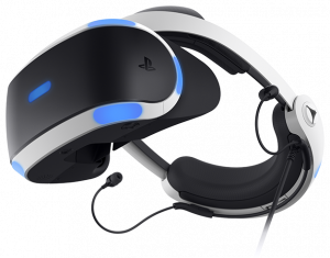
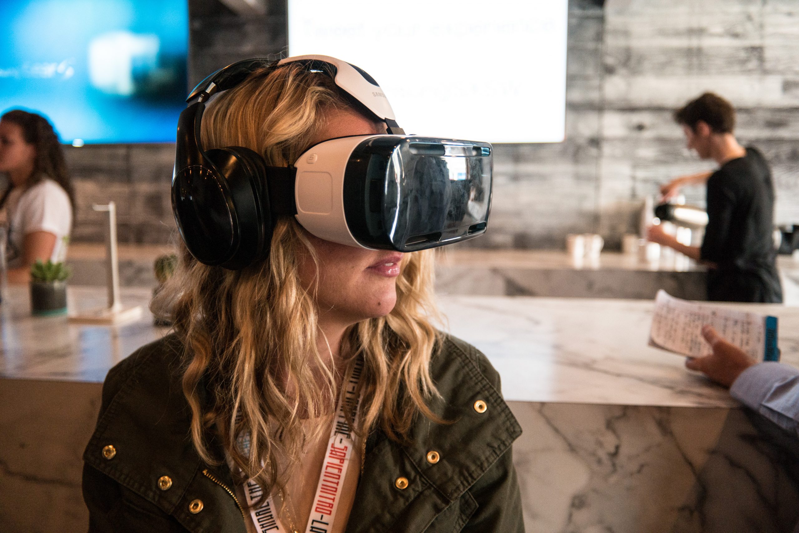
Figure 1. The PC-based HTC Vive (top), game-console-based Sony PlayStation VR (middle) and smartphone-based Samsung Gear VR (bottom) are examples of the varying platform (and vision processing) implementations found in first-generation VR systems (top courtesy Maurizio Pesce, middle courtesy Sony Electronics, bottom courtesy Nan Palmero).
Much the same can be said about computer vision, a broad, interdisciplinary field that uses processing technology to extract useful information from visual inputs by analyzing images and other raw sensor data. Computer vision has mainly been a field of academic research over the past several decades, implemented primarily in complex and expensive systems. Recent technology advances have rapidly moved computer vision applications into the mainstream, as cameras (and the image sensors contained within them) become more feature-rich, as the processors analyzing the video outputs similarly increase in performance, and as the associated software becomes more robust. As these and other key system building blocks such as memory devices also decrease in cost and power consumption, the advances are now paving the way for the proliferation of practical computer vision into diverse applications. Computer vision that is embedded in stand-alone products or applications is often called “embedded vision.”
VR is a key potential growth market for embedded vision, as initial implementations of a subset of the technology’s full potential in first-generation platforms exemplify. Cameras mounted directly on the HMD exterior, and/or in the room in which the VR system is being used, find use in discerning the user’s head, hands’, other body parts’ and overall body locations and motions, thereby enabling the user (in part or in entirety) to be “inserted” into the virtual world. These same cameras can also ensure that a VR user who’s in motion doesn’t collide with walls, furniture or other objects in the room, including other VR users.
Meanwhile, cameras mounted inside the HMD can implement gaze tracking for user interface control, for example, as well as supporting advanced techniques such as foveated rendering and simulated dynamic depth of field that enhance the perceived virtual world realism while simultaneously reducing processing and memory requirements. And by minimizing the overall processing and storage requirements for data coming from both internal and external sensors, as well as by efficiently partitioning the overall load among multiple heterogeneous resources within the overall system architecture, designers are able to optimize numerous key parameters: performance, capacity, bandwidth, power consumption, cost, size, and weight, for example.
User and Environment Mapping Using a Conventional Camera
In order to deliver fully immersive VR, the 3D graphics displayed by a HMD need to be rendered precisely from the user’s viewpoint, and with imperceptible latency. Otherwise, if location inaccuracy or delay is excessive, the user may experience nausea; more generally, any desirable “suspension of disbelief” aspect of the VR experience will be practically unattainable. To measure the location, orientation and motion of the headset, today’s first-generation VR systems at minimum use IMUs (inertial measurement units) such as gyroscopes and accelometers. Such sensors operate just like the ones found in mobile phones – and with smartphone-based VR, in fact, they’re one and the same. Unfortunately, IMUs tend to suffer from location drift, i.e., an ever-increasing discrepancy between where the system thinks the HMD is located versus its actual location. And even under the best of circumstances, they’re not able to deliver the accuracy required for a robust immersive experience.
Higher-end VR systems such as HTC’s Vive, the Oculus Rift, and Sony’s PlayStation VR leverage additional external light transmission and reception devices, enabling more accurate detection and tracking of the HMD and its behavior. Both Oculus and Sony, for example, utilize an array of “tracker” infrared LEDs mounted to the HMD, in conjunction with a room-located camera. With HTC’s Vive the photosensors are installed on the HMD itself, where they detect the horizontal and vertical beams emitted by multiple “Lighthouse” laser base stations. Such light-emitting active systems, typically based on infrared or otherwise non-visible spectrum light such that the human eye doesn’t notice it, have two fundamental drawbacks, however: potential interference from other similar-spectrum illumination sources, and limited range.
An alternative or supplement to IMUs or external active systems for tracking involves mounting one or several small outward-facing cameras on the HMD exterior. HTC’s Vive, in fact, implements such an arrangement, via a single camera located on the front of the HMD. To date, the camera only finds use in the system’s “Chaperone” mode, which optionally provides a live video feed to the HMD in order to safely guide the user away from obstacles. But external cameras (which are also already present in smartphones, therefore readily available to smartphone-based VR setups), in conjunction with vision processors running relevant algorithms, are conceptually capable of much more:
- Tracking of the location and orientation of the headset, in all six degrees of freedom (three directions each of translation and rotation)
- Analyzing the user’s surroundings to prevent collisions with walls, furniture, other VR users, or other obstacles, and
- Capturing and deciphering the position, orientation and motion of the user’s hands and other body parts, along with those of other users in the same environment
Algorithms such as SLAM (simultaneous localization and mapping) and SfM (structure from motion) can accurately determine the headset’s location and other characteristics using only a standard 2D camera. Algorithms such as these detect and track feature points of environment objects in the camera’s view, from one frame to another. Based on the dynamic 2D motion of these feature points, 3D position can be calculated. This determination is conceptually similar to the one made by our brains when we move our heads; objects closer to us move more substantially across our field of view in a given amount of time than do objects in the distance.
The amount and direction of feature points’ motion from frame to frame enable the algorithm to calculate the location and orientation of the camera capturing the images. By knowing the location of the camera, we can then know the location of the HMD, and therefore the user’s location. This data can combine with IMU measurements, using sensor fusion techniques, to obtain an even more accurate VR viewpoint for rendering purposes. Since standard cameras are being used, the setup can account for objects at distances that would be infeasible with infrared-based setups mentioned elsewhere; the HMD can even be reliably used outdoors.
The 3D point cloud of the environment generated by a SLAM, SfM or comparable algorithm also enables the VR system to deduce the 2D distance and even full 3D location of items in the surroundings. This data can find use, for example, in warning the user when he or she gets too close to other objects, including other users, in order to avoid collisions. Keep in mind, however, that rapid head movements can temporarily disrupt the accuracy of the environment scanning process delivered by an HMD-located camera, versus with an alternative room-located camera setup.
If the user’s hands (potentially including individual fingers) and/or other body parts are also capable of being accurately captured by the HMD-based camera, their positions and movements can also be inserted into the virtual world, as well as being used for gesture interface control and other purposes. Whether or not this added capability is feasible depends on the camera’s FoV (field of view), orientation, DoF (depth of field), and other parameters, along with the technology on which it is based.
User and Environment Mapping Using a 3D Sensor
Conventional 2D camera sensors enable a wide range of vision capabilities across a breadth of applications, and are also cost-effective and steadily advancing in various attributes. However, as previously discussed, in order to use them to determine the 3D location of the camera and/or objects in the viewing environment, it’s necessary for one or both to be in motion at the time. In fully static situations, obtaining an accurate determination of the distance from the camera to any particular object can range from difficult to impossible, even if an object is recognized and a model of its linear dimensions versus distance (such as common sizes of humans’ faces) is incorporated in the calculations.
Alternatively, the HMD developer can choose to incorporate one (or more) of several available 3D sensor technologies in the design, each with a corresponding set of strengths and shortcomings for VR and other vision applications. Stereoscopic vision, for example, combines two side-by-side 2D image sensors (mimicking the spacing between a human being’s set of eyes), determining the distance to an object via triangulation, by using the disparity in viewpoints between them when jointly imaging the subject of interest.
Another 3D sensor approach, structured light, is perhaps best known as the technology employed in Microsoft’s first-generation Kinect peripheral for PCs and the Xbox 360 game console. Structured light is an optical 3D scanning method that projects a set of patterns onto an object, capturing the resulting image with an image sensor. The fixed separation offset between the projector and sensor is leveraged in computing the depth to specific points in the scene, again using triangulation algorithms, this time by translating distortion of the projected patterns (caused by surface roughness) into 3D information
A third approach, the ToF (time-of-flight) sensor is an increasingly common approach to depth sensing, found in the second-generation Kinect peripheral as well as Google’s Project Tango platforms and several trendsetting VR HMD prototypes. A ToF system obtains travel-time information by measuring the delay or phase-shift of a modulated optical signal for all pixels in the scene. Generally, this optical signal is situated in the near-infrared portion of the spectrum so as not to disturb human vision.
ToF sensors consist of arrays of pixels, where each pixel is capable of determining the distance to the scene. Each pixel measures the delay of the received optical signal with respect to the sent signal. A correlation function is performed in each pixel, followed by averaging or integration. The resulting correlation value then represents the travel time or delay. Since all pixels obtain this value simultaneously, “snap-shot” 3D imaging is possible.
Modern ToF systems are capable of simultaneously supporting long-range (e.g., environment mapping) and short-range (e.g., hand tracking) functions, with average power consumption below 300mW for combination of the active illumination source and the 3D imager (Figure 2). The imager is capable of operating at multiple concurrent frame rates and other settings, in order to capture multiple independent data streams for different tasks: 45 fps to realize close range hand tracking, for example, while in parallel scanning the environment at 5 fps along with increased exposure time.
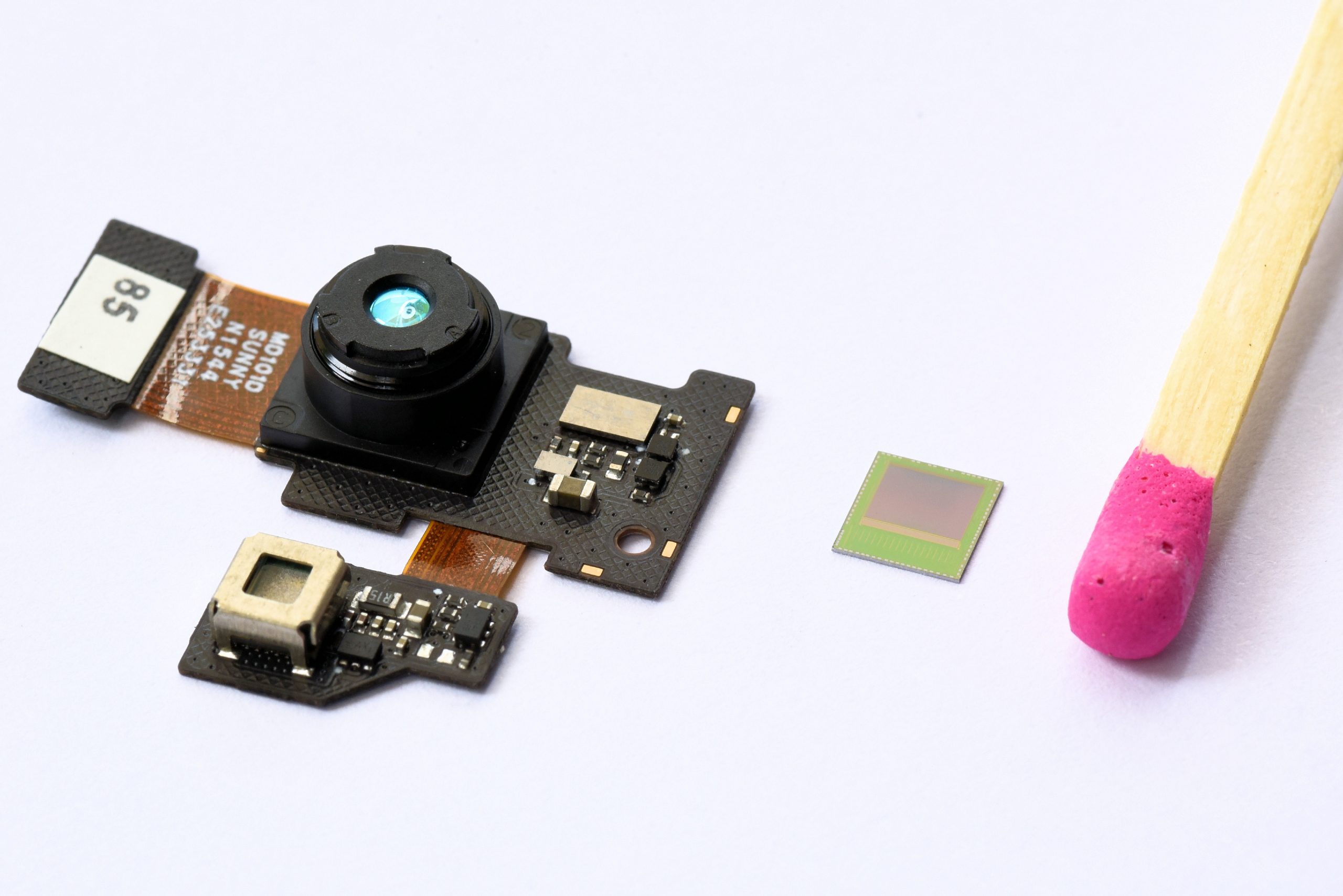
Figure 2. ToF-based 3D cameras, being monocular in nature, enable compact and lightweight system designs as well as delivering cost-effective module calibration and manufacturing capabilities (courtesy Infineon Technologies).
ToF cameras ideally keep the FoV, i.e., the opening angle of the receiving lens, as narrow as possible, typically around 60 degrees horizontal for optimum accuracy. However, a wider FoV of 100 degree or more can be required to deliver seamless and natural movement recognition in the user’s peripheral vision, a VR-unique requirement. Increasing the FoV translates into a decrease in pixel resolution, creating challenges for hand tracking algorithms; it also results in more complex illumination challenges and tradeoffs in the camera lens optical performance. Increasing the pixel resolution, on the other hand, translates into a higher vision processing computational load, larger and heavier imagers and lenses, and greater system cost. Some application-dependent compromise between these two extremes will likely be necessary.
Eye Tracking Capabilities
While outward-facing cameras are important in gaining an understanding of the environment surrounding a user, one or multiple cameras mounted within the HMD and facing the user can be used to understand what the user is looking at and to provide a user interface to the system. Eye tracking enables user gaze to find use as an interaction method, for example, automatically moving the cursor and/or other interface elements to wherever the user is looking at the time. Thanks to humans’ tendencies to rapidly draw their sequential attention to different parts of a scene, gaze-based interfaces may become extremely popular in VR applications.
Eye tracking can also find use in a process known as “foveated rendering,” a technique that can significantly reduce system computational and memory requirements. Within the anatomy of the human retina are found two types of light receptor cells: rods and cones. Rods, being well suited to color discernment and high visual acuity, are located most densely in the fovea, the nexus of the retina. This allocation translates in human perception terms to the center of our field of vision, where images appear crisp and clear.
The second light receptor type, the cone, is not color-sensitive, nor does it have high acuity. However, rods are comparatively more responsive to movement, as well as being more sensitive in low-light conditions. Rods are concentrated in the outer areas of the retina, creating what humans perceive as peripheral vision. Foveated rendering techniques take advantage of this anatomy arrangement by only choosing to render high detail in areas of the scene on which the eyes are currently concentrated, conversely rendering only partial detail in the periphery. This technique significantly reduces graphical rendering overhead, but it requires extremely rapid eye tracking to ensure that the user is never directly viewing a low-detail region.
The sense of immersion can also be improved through eye tracking technology. Current stereoscopic VR systems, for example, do not take into account that the eye’s flexible optics enable users to dynamically and rapidly change focal depth in a scene. When facing a static screen, the user is forced to focus on a static 2D plane, in spite of the fact that 3D content is being displayed. The result is a world that appears 3D, yet the eyes have no ability to focus near or far within it. Focal point detection is therefore necessary in order to realistically re-render a scene relative to the depth of where the user is currently focusing. As with previously discussed foveated rendering, this technique can reduce system computational and memory requirements; in this case, certain areas of the scene are dynamically downscaled based on what particular depth the user is focused on at the time.
Finally, eye tracking can find use in fine-tuning a VR system for any particular user’s vision-related traits. Even minor person-to-person variations in interpupillary distance (eye spacing) can result in degradation to any particular user’s image perception sufficient to result in nausea and/or dizziness (Table 1). The typical VR HMD-expected eye separation is 64 mm, but users can have interpupillary deviations of up to several millimeters around this average value.
|
Gender
|
Sample Size
|
Mean
|
Standard Deviation
|
Min
|
Max
|
Percentile |
||||
|
1st |
5th |
50th |
95th |
99th |
||||||
| Male |
1771 |
64.7 |
3.7 |
52 |
78 |
57 |
59 |
65 |
71 |
74 |
| Female |
2205 |
62.3 |
3.6 |
52 |
76 |
55 |
57 |
62 |
69 |
71 |
Table 1. Interpupillary distance variations (mm), taken from a 1988 U.S. Army survey (courtesy Wikipedia).
The accommodation amplitude (capability of the eye to focus over distance) also varies, not only from person to person but also as a person ages (Figure 3). In addition, the human eye does not naturally remain stationary but is constantly moving (in saccade); any lag or other asynchronous effects in the image being viewed can also contribute to an unnatural and otherwise irritating user experience.
Figure 3. Accommodation amplitude, the eye’s ability to focus over distance, varies not only from person to person but also with age (courtesy Wikipedia).
Implementation Details
One possible eye tracking solution leverages near-infrared (i.e. 800-1000 nm) LED light sources, often multiple of them to improve accuracy, within the VR headset and illuminating one of the user’s eyes. Since a HMD is an enclosed system absent any interfering ambient light, dark-pupil tracking (where the light source can directly illuminate the pupil) is feasible. This technique is more accurate than the alternative bright-pupil solutions used, for example, in ADAS (advanced driver assistance systems) to ascertain a driver alertness and attention to the road ahead.
The LEDs in VR HMDs are pulsed in order to both achieve power savings and improve measurement accuracy. In such a design, a monochrome CMOS image sensor that is tuned for near-IR peak performance can be used. This sensor is capture-synchronized to the pulses of the LED light source(s).
In order to achieve the necessary accuracy and capture performance for this particular application, a global shutter-style image sensor (which captures a full frame of image data at one instant) will likely be required. The alternative and more common rolling shutter-based sensor, wherein portions of the image are sequentially read out of the pixel array across the total exposure time, can result in distortion when images of fast-moving pupils or other objects are captured (Figure 4). Given that the human eye makes hundreds of miniature motions every second, extremely high-speed tracking is required, easily exceeding 100 Hz.
Figure 4. A global shutter-based image sensor (top), unlike the rolling shutter alternative (bottom), delivers the performance and undistorted image quality necessary for eye tracking designs (courtesy ON Semiconductor).
Tracking performance needs also guide system processor selection. While eye tracking algorithms alone can run on general-purpose application processors, dedicated vision processors or other coprocessors may also be required if operations such as head tracking and gesture recognition are also to be supported. Due to the large number of sensors (vision and otherwise) likely present in a VR system, the aggregate bandwidth of their common connection to the host also bears careful consideration.
More generally, eye tracking and other vision functions are key factors in determining overall system requirements, since they (along with foundation graphics rendering) must all operate with extremely low latencies in order to minimize motion sickness effects. In an un-tethered HMD scenario, this requirement means that processing and other resources across numerous vision tasks must be carefully distributed, while retaining sufficient spare GPU headroom for realistic and high-speed rendering. In a tethered setting, one must also consider the total bandwidth requirements of data from incoming HMD-based sensors, through system DRAM, and out to the display via a PC or game console GPU.
Conclusion
VR is one of the hottest products in technology today, and its future is bright both in the current consumer-dominated market and a host of burgeoning commercial applications. System capabilities delivered by vision processing-enabled functions such as environment mapping, user body tracking, and gaze tracking are key features that will transform today’s robust VR market forecasts into tomorrow’s reality. And more generally, vision technology is enabling a wide range of products that are more intelligent and responsive than before, and thus more valuable to users. Vision processing can add valuable capabilities to existing products. And it can provide significant new markets for hardware, software and semiconductor suppliers (see sidebar “Additional Developer Assistance“).
Sidebar: Additional Developer Assistance
The Embedded Vision Alliance, a worldwide organization of technology developers and providers, is working to empower product creators to transform the potential of vision processing into reality. Infineon Technologies, Movidius, ON Semiconductor and videantis, the co-authors of this article, are members of the Embedded Vision Alliance. The Embedded Vision Alliance’s mission is to provide product creators with practical education, information and insights to help them incorporate vision capabilities into new and existing products. To execute this mission, the Embedded Vision Alliance maintains a website providing tutorial articles, videos, code downloads and a discussion forum staffed by technology experts. Registered website users can also receive the Embedded Vision Alliance’s twice-monthly email newsletter, Embedded Vision Insights, among other benefits.
The Embedded Vision Alliance also offers a free online training facility for vision-based product creators: the Embedded Vision Academy. This area of the Embedded Vision Alliance website provides in-depth technical training and other resources to help product creators integrate visual intelligence into next-generation software and systems. Course material in the Embedded Vision Academy spans a wide range of vision-related subjects, from basic vision algorithms to image pre-processing, image sensor interfaces, and software development techniques and tools such as OpenCL, OpenVX and OpenCV, along with Caffe, TensorFlow and other deep learning frameworks. Access is free to all through a simple registration process.
The Embedded Vision Alliance also holds Embedded Vision Summit conferences. Embedded Vision Summits are technical educational forums for product creators interested in incorporating visual intelligence into electronic systems and software. They provide how-to presentations, inspiring keynote talks, demonstrations, and opportunities to interact with technical experts from Embedded Vision Alliance member companies. These events are intended to inspire attendees’ imaginations about the potential applications for practical computer vision technology through exciting presentations and demonstrations, to offer practical know-how for attendees to help them incorporate vision capabilities into their hardware and software products, and to provide opportunities for attendees to meet and talk with leading vision technology companies and learn about their offerings.
The most recent Embedded Vision Summit was held in May 2016, and a comprehensive archive of keynote, technical tutorial and product demonstration videos, along with presentation slide sets, is available on the Embedded Vision Alliance website and YouTube channel. The next Embedded Vision Summit, along with accompanying workshops, is currently scheduled take place on May 1-3, 2017 in Santa Clara, California. Please reserve a spot on your calendar and plan to attend.
By Brian Dipert
Editor-in-Chief, Embedded Vision Alliance
Martin Lass
Product Marketing Manager, Infineon Technologies
Jack Dashwood
Marketing Communications Director, Movidius
Guy Nicholson
Marketing Director, Mobile & Consumer Division, ON Semiconductor
Marco Jacobs
Vice President of Marketing, videantis