This article was originally published at Electronic Engineering Journal. It is reprinted here with the permission of TechFocus Media.
Although augmented reality was first proposed and crudely demonstrated nearly fifty years ago, its implementation was until recently only possible on bulky and expensive computers. Nowadays, however, the fast, low power and cost-effective processors and high resolution, high frame rate image sensors found in mobile electronics devices, along with the increasingly powerful software that these systems run, enables developers to bring AR to the masses.
By Tom Wilson
Vice President, Business Development, CogniVue
Brian Dipert
Editor-in-Chief, Embedded Vision Alliance
Marco Jacobs
Vice President of Marketing, videantis
Tim Droz
Vice President and General Manager, SoftKinetic North America
The prior article in this series, "Embedded Vision on Mobile Devices: Opportunities and Challenges," introduced various embedded vision applications that could be implemented on smartphones, tablet computers and other mobile electronics systems (Reference 1). In this and future articles, we'll delve into greater implementation detail on each of the previously discussed applications. Specifically, this article will examine the processing requirements for vision-based tracking in AR (augmented reality), along with the ability of mobile platforms to address these requirements. Future planned articles in the series will explore face recognition, gesture interfaces and other applications.
Computer graphics pioneer Ivan Sutherland established the basic concepts of AR as known today in his seminal 1968 paper “A Head-Mounted Three Dimensional Display” (Reference 2). Sutherland wrote, “The fundamental idea is to present the user with a perspective image which changes as he moves. The displayed material can be made either to hang disembodied in space or to coincide with maps, desktops, walls, or the keys of a typewriter.” (Figure 1) Sutherland’s visionary impact is clear when you realize that his work occurred at a time when computer graphics was in its infancy and displays could only render very low-resolution lines.
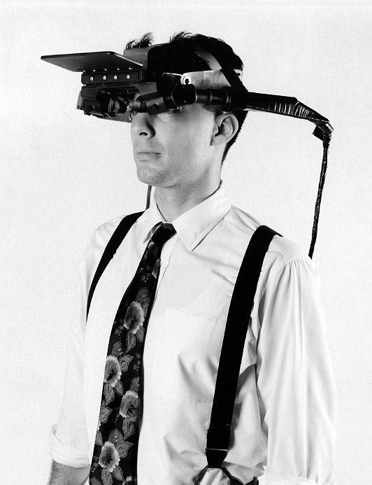
Figure 1. Computer graphics pioneer Ivan Sutherland first demonstrated a crude augmented reality prototype nearly 50 years ago.
The phrase “Augmented Reality,” however, came from researcher Tom Caudell, coined in 1992 while he was working at Boeing. In searching for ways to improve the aviation company’s manufacturing and engineering processes, Caudell applied virtual reality technology techniques and came up with software that overlaid the positions of cables on images of the aircraft.
Initial AR implementations were predominantly PC-based, but AR began "going mobile" in the late 1990s, when smartphones and tablets first became powerful enough to run relevant applications. Mobile electronics devices are ideal AR platforms in part because they include numerous sensors that support various AR facilities. They also provide high performance processors, robust 3D graphics rendering capabilities, abundant memory and storage facilities, high-resolution displays, and high-speed wireless connectivity to access the "cloud" for both data and supplemental processing facilities (Reference 3).
Embedded Vision Enhancements
While inertia (accelerometer, gyroscope) and location (GPS, Wi-Fi, magnetometer, barometer) data can be used to identify the pose (i.e. position and orientation) of a mobile electronics device with reasonable precision, camera-captured and embedded vision-based information is also a common and increasingly important aspect of AR systems. Various approaches to vision-based pose estimation exist, becoming more sophisticated and otherwise evolving over time. The most basic technique uses pre-defined fiducial markers as a means of enabling the feature tracking system to determine device pose (Reference 4). Figure 2 shows a basic system diagram for marker-based processing in AR. The tracking function, the essence of the system, outputs an estimate of the pose of the camera in real time based on what it “sees”.
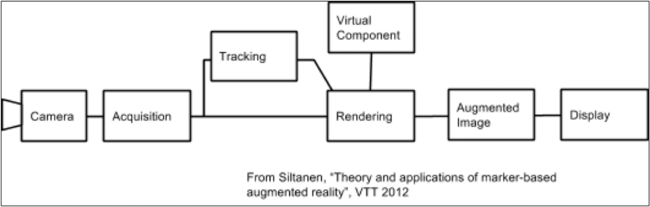
Figure 2. This system flow details the multiple steps involved in implementing marker-based augmented reality.
Markers are a special case of a feature, a common term in computer vision (and now embedded vision), defined by Wikipedia as "a piece of information which is relevant for solving the computational task related to a certain application." (Reference 5) (“Embedded vision,” as introduced in our previous article, refers to the practical implementation of computer vision functions in embedded systems, mobile devices, special-purpose PCs, and the "cloud"). Since markers are easily detectable due to their unique shape and color, and since they are located in a visual plane, they can assist in rapid pose calculation. Their high contrast enables easier detection, and four known marker points allows for unambiguous calculation of the camera pose (Reference 6). Most markers are comprised of elementary patterns of black and white squares. The four known points are critical to enable not only marker decoding but also lens distortion correction (Reference 7). Figure 3 shows two marker examples from the popular ARToolKit open source tracking library used in the creation of AR applications.
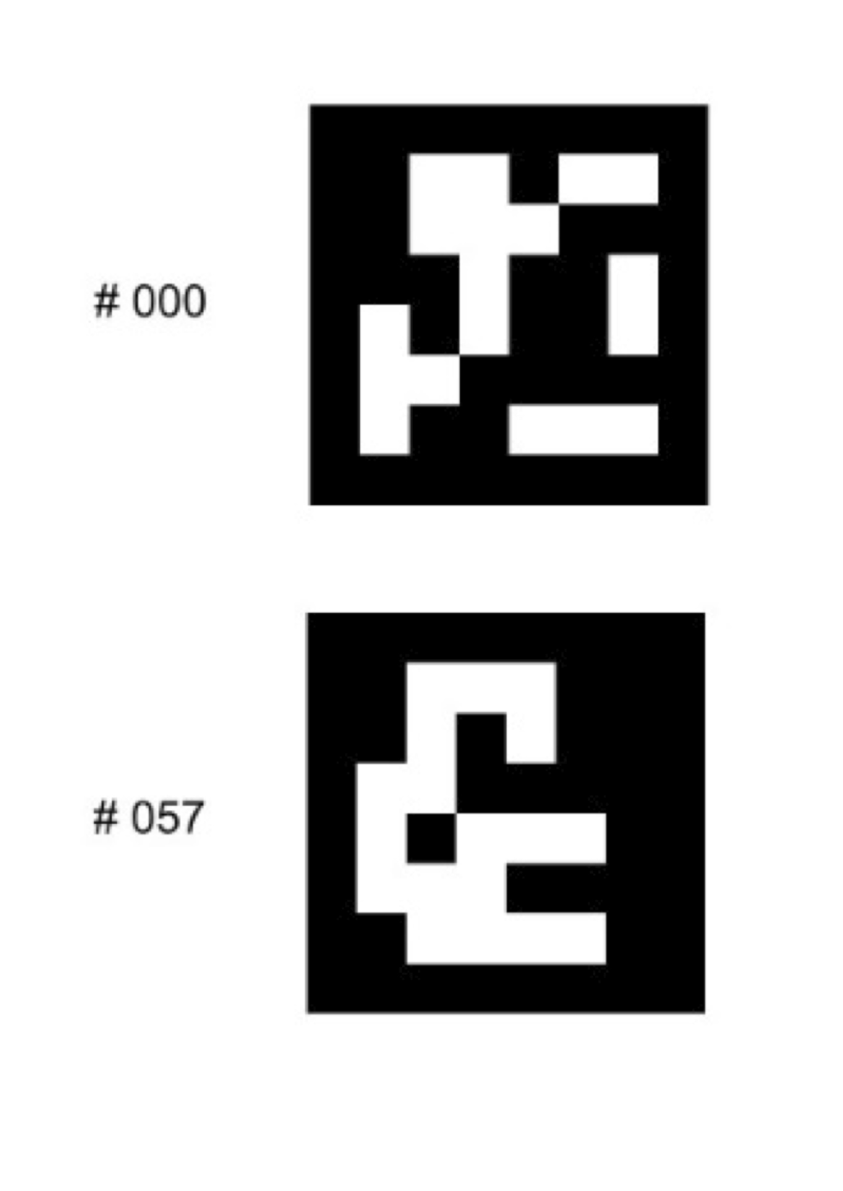
Figure 3. The ARToolKit open source library supports the development of fiducial markers.
While marker-based AR is a relatively basic approach for vision-based pose estimation, a review of the underlying embedded vision processing algorithms is especially worthwhile in the context of small, power-limited, mobile platforms. Such an understanding can also assist in extrapolating the requirements if more demanding pose estimation approaches are required in a given application. The basic vision processing steps for marker-based AR involve:
- Converting the input image to grayscale
- Performing binary threshold operations in order to generate a high contrast black and white image
- Detecting contours in order to "bound" the marker
- Identifying marker candidates, and then
- Performing distortion correction in order to enable accurate marker decode
These steps encompass fundamental computer vision and image processing functions such as those found in the OpenCV open source software library (Reference 8). Resources are also available to show you how to build a marker-based AR application for iOS or another operating system (Reference 9).
It's important for an AR application to work in real-time, ideally delivering 25 fps (frames per second) or higher. This means that within 40 ms (or less), the system needs to capture each image, detect and decode one or multiple markers within it, and render the scene augmentation. Image capture latency is not insignificant; on its own it can potentially create many milliseconds' worth of system latency (Reference 10). For example, the iPhone 4 in the study documented in Reference 10 requires 17.4 ms just for image capture, translating into latencies in the range of 180 ms for marker detection and decoding. Algorithm optimization may allow for performance improvements. Indeed, the alternative Android platform described in Reference 10 was reportedly capable of ~6 fps. More advanced smartphones and tablets processors, combined with additional algorithm optimization, would likely enable the sub-40 ms latency previously mentioned as required for real-time performance.
Marker-Free Complexity
The design problem becomes significantly more complicated, however, with “marker-less” AR. Such implementations are perhaps obviously appealing for use in real-life settings that don't include pre-determined markers. Without fiducial markers, the camera position must be determined through “natural feature tracking” using feature-based detection, tracking, and matching. This approach is associated with the SLAM (simultaneous localization and mapping) techniques that have been developed in robotic research (Reference 11). SLAM attempts to first localize the camera in a map of the environment and then find the pose of the camera relative to that map. Visual tracking plays a key role in this and is especially difficult without any a priori knowledge of the camera’s location and orientation. A variety of feature trackers and feature matching algorithms exist for this purpose, each with varying computational requirements and other strengths and shortcomings.
Feature detectors can be roughly categorized based on the types of features they detect: edges (e.g. Canny), corners (e.g. Harris), blobs (e.g. MSER, or maximally stable extremal regions), and patches. However, some detectors use multiple types of features. For example, the SUSAN (smallest univalue segment assimilating nucleus) approach employs both edge and corner detection. Ultimately the selection and use of a particular feature detector has a great deal to do with its performance and its suitability for a real-time embedded environment. For example, FAST, a commonly used corner-detection algorithm, produces relatively reliable results and is also computationally "light" compared to other approaches (Reference 12).
Feature tracking and motion estimation both attempt to solve the problem of selecting features and then tracking them from frame to frame. "Dense" optical flow involves the matching of every pixel in consecutive image frames, but "sparse" optical flow (using only selected features) is more typically used in embedded applications in order to reduce the computational load (Reference 13). This simplification is particularly necessary in the context of a mobile computing platform that runs off a diminutive battery. The Kanade-Lucas-Tomasi (KLT) feature tracker, available in OpenCV, is one widely used optical flow algorithm.
Feature Matching
Matching is a more elaborate means of establishing feature correspondence, used in situations where there is higher expectation of relative motion and a greater likelihood of notable change in illumination, rotation, and other environment and feature characteristics. The inter-frame matching goal is typically accomplished via either template matching or descriptor matching techniques. Template matching is used for pixel-wise correlation, especially when one image is assumed to be a simple spatial translation of another, e.g. for disparity mapping used with stereo depth cameras, which we'll discuss further shortly (Reference 14). A key issue with template matching is that reliability can degrade due to between-frame changes in scene illumination or camera orientation.
These issues are resolved with feature descriptors, which are calculated to distinctively characterize a feature and should therefore be illumination-, rotation-, and camera angle-invariant. For example, SIFT (scale invariant feature transform) is widely used for feature detection and tracking applications. Note that SIFT is relatively compute-intensive compared to FAST and therefore runs at lower frame rates on mobile platforms (e.g. 2 fps vs 20 fps, see Reference 12). You might expect this frame rate to improve with optimization, and indeed with the combination of GPU acceleration and algorithm enhancements, processing performance can be increased to nearly 10 fps in similar mobile settings (Reference 15).
With marker-less AR, however, feature detection and matching is only part of the overall processing chain. Recall from the earlier discussion that visually derived information from functions such as optical flow and feature matching are then used in a SLAM process to determine the camera's location in a map (using models accessed from the cloud via a network connection, for example), as well as the camera's pose relative to that same map. Recall as well that to ensure real-time performance at reasonable frame rates, the overall processing latency must be no more than 40 ms. This latency is the sum of the following steps:
- Image capture
- Image processing (conversion to grayscale, perhaps along with other image transformations)
- Feature detection (via FAST or another detector)
- Optical flow and feature tracking (e.g. KLT), or a more robust feature-matching implementation with descriptors (SIFT or SURF, i.e. Speeded Up Robust Features, or some variant of these)
- Mapping and pose estimation
As latency increases, the achievable frame correspondingly diminishes.
Depth-Sensing Cameras, Vision-Tailored Processors
Note that the earlier listed processing chain assumes a 2D implementation. Absent awareness of the distance from the camera to the objects in view, the AR application can only render the virtual objects onto a plane. In such a case, real-world objects that are not planar will not blend correctly with the artificial 3D model, resulting in artifacts. While a 2D image sensor in conjunction with markers can ascertain an approximation of the distance to those markers, a more robust AR experience is achievable with one of several types of depth-sensing cameras, such as those based on SoftKinetic's time-of-flight technology (Reference 16).
The depth maps produced by such cameras enable a more accurate merging of real-world imagery with a 3D model. Using a depth camera, the virtual objects can be blended correctly and can even interact with non-planar surfaces, yielding a much higher-quality user experience. However, the disparity mapping and matching necessary with a stereo image sensor array (one of the common 3D camera approaches), for example, involves notably compute-intensive computer vision functions that would be incremental to feature detection, tracking, and (potentially also) object classification (Reference 17). Compare this cumulative vision processing burden with the previously described elementary marker-based AR, and the challenge of embedded vision processing for natural feature tracking and SLAM on mobile platforms becomes quite evident.
Keep in mind that this intensive and sophisticated processing must also be done at very low power consumption levels. For AR applications to become ubiquitous, they must enable "always on" use cases that don’t involve draining the mobile electronics device's battery in a few minutes. For example, consider the amount of hardware active during a visual tracking AR application
- Image sensor
- ISP (image signal processor)
- Embedded vision processor
- GPU for graphics overlay
- Host CPU for application processing
- Communications DSP, doing baseband processing for network access for maps or models
- Wi-Fi and/or cellular data transmitters and receivers, and
- The system display
One compelling option for implementing the embedded vision portion of the AR function is a dedicated-function vision processor that enables high performance at low power consumption. Vision processing cores for image analysis, suitable for SoC integration, are already available from multiple companies, such as CogniVue and videantis. Allocating this embedded vision processing to dedicated function cores also enables more power-efficient use of CPUs and GPUs, enabling them to focus their attention on what they were designed to do well: higher-level control processing and graphics.
Industry Alliance Assistance
Embedded vision technology has the potential to enable a wide range of electronic products that are more intelligent and responsive than before, and thus more valuable to users, such as the augmented reality-capable mobile devices discussed in this article. Embedded vision processing can add helpful features to existing products. And it can provide significant new markets for hardware, software and semiconductor manufacturers. The Embedded Vision Alliance, a worldwide organization of technology developers and providers, is working to empower engineers to transform this potential into reality. CogniVue, SoftKinetic and videantis, the co-authors of this article, are members of the Embedded Vision Alliance.
First and foremost, the Alliance's mission is to provide engineers with practical education, information, and insights to help them incorporate embedded vision capabilities into new and existing products. To execute this mission, the Alliance maintains a website providing tutorial articles, videos, code downloads and a discussion forum staffed by technology experts. Registered website users can also receive the Alliance’s twice-monthly email newsletter, among other benefits.
In addition, the Embedded Vision Alliance offers a free online training facility for embedded vision product developers: the Embedded Vision Academy. This area of the Alliance website provides in-depth technical training and other resources to help engineers integrate visual intelligence into next-generation embedded and consumer devices. Course material in the Embedded Vision Academy spans a wide range of vision-related subjects, from basic vision algorithms to image pre-processing, image sensor interfaces, and software development techniques and tools such as OpenCV. Access is free to all through a simple registration process.
The Embedded Vision Summit
On Thursday, May 29, 2014, in Santa Clara, California, the Alliance will hold its fourth Embedded Vision Summit. Embedded Vision Summits are technical educational forums for engineers interested in incorporating visual intelligence into electronic systems and software. They provide how-to presentations, inspiring keynote talks, demonstrations, and opportunities to interact with technical experts from Alliance member companies. These events are intended to:
- Inspire engineers' imaginations about the potential applications for embedded vision technology through exciting presentations and demonstrations.
- Offer practical know-how for engineers to help them incorporate vision capabilities into their products, and
- Provide opportunities for engineers to meet and talk with leading embedded vision technology companies and learn about their offerings.
The Embedded Vision Summit West will be co-located with the Augmented World Expo, a three-day event covering augmented reality, wearable computing, and the "Internet of Things". Attendees of the Embedded Vision Summit West will have the option of also attending the full Augmented World Expo conference or accessing the Augmented World Expo exhibit floor at a discounted price. Please visit the event page for more information on the Embedded Vision Summit West and associated hands-on workshops, such as a detailed agenda, keynote, technical tutorial and other presentation details, speaker biographies, and online registration.
References:
- https://www.embedded-vision.com/platinum-members/embedded-vision-alliance/embedded-vision-training/documents/pages/embedded-vision-mobile-devices
- http://90.146.8.18/en/archiv_files/19902/E1990b_123.pdf
- https://www.embedded-vision.com/platinum-members/bdti/embedded-vision-training/videos/pages/december-2012-embedded-vision-alliance-m
- http://en.wikipedia.org/wiki/Fiducial_marker
- http://en.wikipedia.org/wiki/Feature_(computer_vision)
- http://www.haralick.org/journals/three_point_perspective.pdf
- https://www.embedded-vision.com/platinum-members/bdti/embedded-vision-training/documents/pages/lens-distortion-correction
- https://www.embedded-vision.com/introduction-computer-vision-using-opencv
- http://www.packtpub.com/article/marker-based-augmented-reality-on-iPhone-or-iPad
- http://informatica.uv.es/~pmorillo/papers/pmorillo_dsrt11.pdf
- https://www.embedded-vision.com/platinum-members/embedded-vision-alliance/embedded-vision-training/documents/pages/robotics
- http://eprints2.utem.edu.my/8556/1/17Vol47No1_3.pdf
- https://www.embedded-vision.com/platinum-members/bdti/embedded-vision-training/videos/pages/demonstration-optical-flow-algorithm-fpg
- https://www.embedded-vision.com/platinum-members/cognivue/embedded-vision-training/videos/pages/oct-2013-embedded-vision-summit
- http://www.ece.rice.edu/~gw2/pdf/icassp2013_mobile_sift.pdf
- https://www.embedded-vision.com/platinum-members/embedded-vision-alliance/embedded-vision-training/documents/pages/3d-sensors-depth-discernment
- https://www.embedded-vision.com/platinum-members/cognivue/embedded-vision-training/videos/pages/oct-2013-embedded-vision-summit
Tom Wilson is Vice President of Business Development at CogniVue Corporation, with more than 20 years of experience in various applications such as consumer, automotive, and telecommunications. He has held leadership roles in engineering, sales and product management, and has a Bachelor’s of Science and PhD in Science from Carleton University, Ottawa, Canada.
Brian Dipert is Editor-In-Chief of the Embedded Vision Alliance. He is also a Senior Analyst at Berkeley Design Technology, Inc., which provides analysis, advice, and engineering for embedded processing technology and applications, and Editor-In-Chief of InsideDSP, the company's online newsletter dedicated to digital signal processing technology. Brian has a B.S. degree in Electrical Engineering from Purdue University in West Lafayette, IN. His professional career began at Magnavox Electronics Systems in Fort Wayne, IN; Brian subsequently spent eight years at Intel Corporation in Folsom, CA. He then spent 14 years at EDN Magazine.
Marco Jacobs, Vice President of Marketing at videantis, has over 15 years of experience in the semiconductor IP industry and multimedia applications. At videantis, he is responsible for corporate and product marketing and works with Tier 1 semiconductor manufacturers to bring novel, higher-quality video and vision applications to their customers. Prior to joining videantis, Marco was VP of Marketing at Vector Fabrics, Director of Multimedia Marketing at ARC, held management positions at semiconductor startups Silicon Hive and BOPS, and was a software architect at Philips. Marco studied computer science at the Delft University of Technology in the Netherlands and at the University of North Carolina, Chapel Hill. He holds 7 issued patents.
Tim Droz heads the SoftKinetic U.S. organization, delivering 3D TOF (time-of-flight) and gesture solutions to international customers, such as Intel and Texas Instruments. Prior to SoftKinetic, he was Vice President of Platform Engineering and head of the Entertainment Solutions Business Unit at Canesta, subsequently acquired by Microsoft. His pioneering work extends into all aspects of the gesture and 3D ecosystem, including 3D sensors, gesture-based middleware and applications. Tim earned a BSEE from the University of Virginia, and a M.S. degree in Electrical and Computer Engineering from North Carolina State University.