By Michael Brading
Automotive and Industrial Business Unit Chief Technology Officer, Aptina Imaging
Kenneth Salsman
Director of New Technology, Aptina Imaging
Manjunath Somayaji
Staff Imaging Scientist, Aptina Imaging
Brian Dipert
Editor-in-Chief, Embedded Vision Alliance
Senior Analyst, BDTI
Tim Droz
Vice President, US Operations, SoftKinetic
Daniël Van Nieuwenhove
Chief Technical Officer, SoftKinetic
Pedro Gelabert
Senior Member of the Technical Staff and Systems Engineer, Texas Instruments
This article is an expanded version of one originally published at EE Times' Embedded.com Design Line. It is reprinted here with the permission of EE Times.
The ability to sense objects in three dimensions can deliver both significant new and significantly enhanced capabilities to vision system designs. Several depth sensor technology alternatives exist to implement this potential, however, each with strengths, shortcomings and common use cases.
The term "embedded vision" refers to the use of computer vision in embedded systems, mobile devices, PCs and the cloud. Stated another way, "embedded vision" refers to systems that extract meaning from visual inputs. Historically, such image analysis technology has typically only been found in complex, expensive systems, such as military equipment, industrial robots and quality-control inspection systems for manufacturing. However, cost, performance and power consumption advances in digital integrated circuits such as processors, memory devices and image sensors are now paving the way for the proliferation of embedded vision into high-volume applications.
With a few notable exceptions, such as Microsoft's Kinect game console and computer peripheral, the bulk of today's embedded vision system designs employ 2-D image sensors. 2-D sensors enable a tremendous breadth and depth of vision capabilities. However, their inability to discern an object's distance from the sensor can make it difficult or impossible to implement some vision functions. And clever workarounds, such as supplementing 2-D sensed representations with already known 3-D models of identified objects (human hands, bodies or faces, for example) can be too constraining in some cases.
In what kinds of applications would full 3-D sensing be of notable value versus the more limited 2-D alternative? Consider, for example, a gesture interface implementation. The ability to discern motion not only up-and-down and side-to-side but also front-to-back greatly expands the variety, richness and precision of the suite of gestures that a system can decode. Or consider a biometrics application: face recognition. Depth sensing is valuable in determining that the object being sensed is an actual person's face, versus a photograph of that person's face; alternative means of accomplishing this objective, such as requiring the biometric subject to blink during the sensing cycle, are inelegant in comparison.
ADAS (automotive advanced driver assistance system) applications that benefit from 3-D sensors are abundant. You can easily imagine, for example, the added value of being able to determine not only that another vehicle or object is in the roadway ahead of or behind you, but also to accurately discern its distance from you. Precisely determining the distance between your vehicle and a speed-limit-change sign is equally valuable in ascertaining how much time you have to slow down in order to avoid getting a ticket. The need for accurate three-dimensional no-contact scanning of real-life objects, whether for a medical instrument, in conjunction with increasingly popular "3-D printers", or for some other purpose, is also obvious. And plenty of other compelling applications exist: 3-D videoconferencing, manufacturing line "binning" and defect screening, etc.
Stereoscopic Vision
Stereoscopic vision, combining two 2-D image sensors, is currently the most common 3-D sensor approach. Passive (i.e. relying solely on ambient light) range determination via stereoscopic vision utilizes the disparity in viewpoints between a pair of near-identical cameras to measure the distance to a subject of interest. In this approach, the centers of perspective of the two cameras are separated by a baseline or IPD (inter-pupillary distance) to generate the parallax necessary for depth measurement (Figure 1). Typically, the cameras’ optical axes are parallel to each other and orthogonal to the plane containing their centers of perspective.
Figure 1. Relative parallax shift as a function of distance. Subject A (nearby) induces a greater parallax than subject B (farther out), against a common background.
For a given subject distance, the IPD determines the angular separation θ of the subject as seen by the camera pair and thus plays an important role in parallax detection. It dictates the operating range within which effective depth discrimination is possible, and it also influences depth resolution limits at various subject distances. A relatively small baseline (i.e. several millimeters) is generally sufficient for very close operation such as gesture recognition using a mobile phone. Conversely, tracking a person’s hand from across a room requires the cameras to be spaced further apart. Generally, it is quite feasible to achieve depth accuracies of less than an inch at distances of up to 10 feet.
Implementation issues that must be considered in stereoscopic vision-based designs include the fact that when subject is in motion, accurate parallax information requires precise camera synchronization, often at fast frame rates (e.g., 120 fps). The cameras must be, at minimum, synchronized during the commencement of a frame capture sequence. An even better approach involves using a mode called “gen-lock,” where the line-scan timings of the two imagers are synchronized. Camera providers have developed a variety of sync-mode (using a master-slave configuration) and gen-lock-mode sensors for numerous applications, including forward-looking cameras in automobiles.
Alignment is another critical factor in stereoscopic vision. The lens systems must be as close to identical as possible, including magnification factors and pitch-roll-yaw orientations. Otherwise, inaccurate parallax measurements will result. Likewise, misalignment of individual lens elements within a camera module could cause varying aberrations, particularly distortions, resulting in false registration along all spatial dimensions. Occlusion, which occurs when an object or portion of an object is visible to one sensor but not to the other –is another area of concern, especially at closer ranges, but this is a challenge common in most depth-sensing techniques.
Structured Light
Microsoft's Kinect is today's best-known structured light-based 3-D sensor. The structured light approach, like the time-of-flight technique to be discussed next, is one example of an active non-contact scanner; non-contact, because scanning does not involve the sensor physically touching an object’s surface, and active, because it generates its own electromagnetic radiation and analyzes the reflection of this radiation from the object. Typically, active non-contact scanners use lasers, LEDs, or lamps in the visible or infrared radiation range. Since these systems illuminate the object, they do not require separate controlled illumination of the object for accurate measurements. An optical sensor captures the reflected radiation.
Structured light is an optical 3-D scanning method that projects a set of patterns onto an object, capturing the resulting image with an image sensor. The image sensor is offset from the projected patterns. Structured light replaces the previously discussed stereoscopic vision sensor's second imaging sensor with a projection component. Similar to stereoscopic vision techniques, this approach takes advantage of the known camera-to-projector separation to locate a specific point between them and compute the depth with triangulation algorithms. Thus, image processing and triangulation algorithms convert the distortion of the projected patterns, caused by surface roughness, into 3-D information (Figure 2).
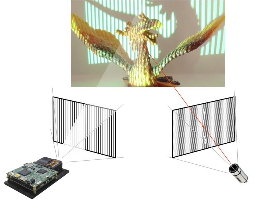
Figure 2. An example structured light implementation using a DLP-based modulator.
Three main types of scanners are used to implement structured light techniques: laser scanners, fixed-pattern scanners, and programmable-pattern scanners. Laser scanners typically utilize a laser in conjunction with a gyrating mirror to project a line on an object. This line is scanned at discrete steps across the object’s surface. An optical sensor, offset from the laser, captures each line scan on the surface of the object.
Fixed-pattern scanners utilize a laser or LED with a diffractive optical element to project a fixed pattern on the surface of the object. An optical sensor, offset from the laser, captures the projected pattern on the surface of the object. In contrast to a laser scanner, the optical sensor of a fixed-pattern scanner captures all of the projected patterns at once. Fixed-pattern scanners typically use pseudorandom binary patterns, such as those based on De Bruijn sequences or M-arrays. These pseudorandom patterns divide the acquired image into a set of sub-patterns that are easily identifiable, since each sub-pattern appears at most once in the image. Thus, this technique uses a spatial neighborhood codification approach.
Programmable-pattern scanners utilize laser, LED, or lamp illumination along with a digital spatial light modulator to project a series of patterns on the surface of the object. An optical sensor, offset from the projector, captures the projected pattern on the surface of the object. Similar to a fixed-pattern scanner, the optical sensor of the programmable-pattern scanner captures the entire projected pattern at once. The primary advantages of programmable-pattern structured light scanners versus fixed-pattern alternatives involve the ability to obtain greater depth accuracy via the use of multiple patterns, as well as to adapt the patterns in response to factors such as ambient light, the object’s surface, and the object’s optical reflection.
Since programmable-pattern structured light requires the projection of multiple patterns, a spatial light modulator provides a cost effective solution. Several spatial light modulation technologies exist in the market, including LCD (liquid crystal display), LCoS (liquid crystal on silicon), and DLP (digital light processing). DLP-based spatial light modulators' capabilities include fast and programmable pattern rates up to 20,000 frames per second, with 1-bit to 8-bit grey scale support, high contrast patterns, consistent and reliable performance over time and temperature, no motors or other fragile moving components, and available solutions with optical efficiency from 365 to 2500 nm wavelengths.
Structured light-based 3-D sensor designs must optimize, and in some cases balance trade-offs between, multiple implementation factors. Sufficient illumination wavelength and power are needed to provide adequate dynamic range, based on ambient illumination and the scanned object's distance and reflectivity. Algorithms must be optimized for a particular application, taking into account the object's motion, topology, desired accuracy, and scanning speed. Adaptive object analysis decreases scanning speed, for example, but provides for a significant increase in accuracy. The resolution of the spatial light modulator and imaging sensor must be tailored to extract the desired accuracy from the system. This selection process primarily affects both cost and the amount of computation required.
Scanning speed is predominantly limited by image sensor performance; high-speed sensors can greatly increase system cost. Object occlusion can present problems, since the pattern projection might shadow a feature in the topology and thereby hide it from the captured image. Rotation of the scanned object, along with multiple analysis and stitching algorithms, provides a good solution for occlusion issues. Finally, system calibration must be comprehended in the design. It's possible to characterize and compensate for projection and imaging lens distortions, for example, since the measured data is based on code words, not on an image's disparity.
Time-of-Flight
An indirect ToF (time-of-flight) system obtains travel-time information by measuring the delay or phase-shift of a modulated optical signal for all pixels in the scene. Generally, this optical signal is situated in the near-infrared portion of the spectrum so as not to disturb human vision. The ToF sensor in the system consists of an array of pixels, where each pixel is capable of determining the distance to the scene.
Each pixel measures the delay of the received optical signal with respect to the sent signal (Figure 3). A correlation function is performed in each pixel, followed by averaging or integration. The resulting correlation value then represents the travel time or delay. Since all pixels obtain this value simultaneously, "snap-shot" 3-D imaging is possible.
Figure 3. Varying sent-to-received delays correlate to varying distances between a time-of-flight sensor and portions of an object or scene.
As with the other 3-D sensor technologies discussed in this article, a number of challenges need to be addressed in implementing a practical ToF-based system. First, the depth resolution (or noise uncertainty) of the ToF system is linked directly to the modulation frequency, the efficiency of correlation, and the SNR (signal to noise ratio). These specifications are primarily determined by the quality of the pixels in the ToF sensor. Dynamic range must be maximized in order to accurately measure the depth of both close and far objects, particularly those with differing reflectivities.
Another technical challenge involves the suppression of any background ambient light present in the scene, in order to prevent sensor saturation, and enable robust operation in both indoor and outdoor environments. Since more than one ToF system can be present, inter-camera crosstalk must also be eliminated. And all of these challenges must be addressed while keeping the pixel size small enough to obtain the required lateral resolution without compromising pixel accuracy.
Technology Comparisons
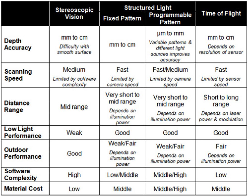
No single 3-D sensor technology can meet the needs of every application (Table A). Stereoscopic vision technology demands high software complexity in order to process and analyze highly precise 3-D depth data in real time, thereby typically necessitating DSPs (digital signal processors) or multi-core processors. Stereoscopic vision sensors themselves, however, can be cost-effective and fit in small form factors, making them a good choice for consumer electronics devices such smartphones and tablets. But they typically cannot deliver the high accuracy and fast response time possible with other 3-D sensor technologies, so they may not be the optimum choice for manufacturing quality assurance systems, for example.
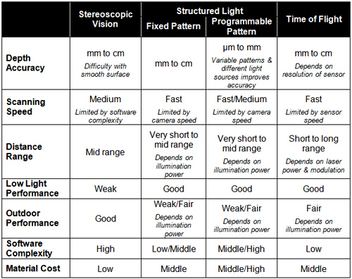
Table A. 3-D vision sensor technology comparisons.
Structured light technology is an ideal solution for 3-D object scanning, including integration with 3-D CAD (computer-aided design) systems. And structured light systems are often superior at delivering high levels of accuracy with less depth noise in indoor environments. The highly complex algorithms associated with structured light sensors can be handled by hard-wired logic, such as ASICs and FPGAs, but these approaches often involve expensive development and device costs (NRE and/or per-component). The high computation complexity can also result in slower response times.
ToF systems are tailored for device control in application areas that need fast response times, such as manufacturing and consumer electronics devices. ToF systems also typically have low software complexity. However, they integrate expensive illumination parts, such as LEDs and laser diodes, as well as costly high-speed interface-related parts, such as fast ADCs, fast serial/parallel interfaces and fast PWM (pulse width modulation) drivers, all of which increase bill-of-materials costs.
Industry Alliance Assistance
Determining the optimum 3-D sensor technology for your next embedded vision design is not a straightforward undertaking. The ability to tap into the collective knowledge and experiences of a community of your engineering peers can therefore be quite helpful, along with the ability to harness the knowledge of various potential technology suppliers. These are among the many resources offered by the Embedded Vision Alliance, a worldwide organization of semiconductor, software and services developers and providers, poised to assist you in rapidly and robustly transforming your next-generation ideas into shipping-product reality.
The Alliance’s mission is to provide engineers with practical education, information, and insights to help them incorporate embedded vision capabilities into products. To execute this mission, the Alliance has developed a Web site (www.Embedded-Vision.com) with tutorial articles, videos, code downloads, and a discussion forum staffed by a diversity of technology experts. For more information on the Embedded Vision Alliance, please email [email protected] or call +1 (925) 954-1411.
Michael Brading is Chief Technical Officer of the Automotive Industrial and Medical business unit at Aptina Imaging. Prior to that, Mike was Vice President of Engineering at InVisage Technologies. Mike has more than 20 years of integrated circuit design experience, working with design teams all over the world. Michael was also previously the director of design and applications at Micron Technology, and the director of engineering for emerging markets. And before joining Micron Technology, he also held engineering management positions with LSI Logic. Michael has a B.S. in communication engineering from the University of Plymouth.
Kenneth Salsman is the Director of New Technology at Aptina Imaging. Kenneth has been a researcher and research manager for more than 30 years at companies such as Bell Laboratories and the Sarnoff Research Center. He was also Director of Technology Strategy for Compaq Research, and a Lead Scientist at both Compaq and Intel. Kenneth has a Masters degree in Nuclear Engineering, along with an extensive background in optical physics. He was also Chief Science Officer at Innurvation, where he developed a pill sized HD optical scanning system for imaging the gastrointestinal tract. He holds more than 48 patents.
Manjunath Somayaji is the Imaging Systems Group manager at Aptina Imaging, where he leads algorithm development efforts on novel multi-aperture/array-camera platforms. For the past ten years, he has worked on numerous computational imaging technologies such as multi-aperture cameras and extended depth of field systems. He received his M.S. degree and Ph.D. from Southern Methodist University (SMU) and his B.E. from the University of Mysore, all in Electrical Engineering. He was formerly a Research Assistant Professor in SMU's Electrical Engineering department. Prior to SMU, he worked at OmniVision-CDM Optics as a Senior Systems Engineer.
Brian Dipert is Editor-In-Chief of the Embedded Vision Alliance. He is also a Senior Analyst at Berkeley Design Technology, Inc., which provides analysis, advice, and engineering for embedded processing technology and applications, and Editor-In-Chief of InsideDSP, the company's online newsletter dedicated to digital signal processing technology. Brian has a B.S. degree in Electrical Engineering from Purdue University in West Lafayette, IN. His professional career began at Magnavox Electronics Systems in Fort Wayne, IN; Brian subsequently spent eight years at Intel Corporation in Folsom, CA. He then spent 14 years at EDN Magazine.
Tim Droz is the Vice President of US Operations at SoftKinetic. He joined SoftKinetic in 2011 after 10 years at Canesta, where he was Vice President of Platform Engineering and head of the Entertainment Solutions Business Unit. Before then, Tim was Senior Director of Engineering at Cylink. Tim also earlier led hardware development efforts in embedded and web-based signature capture payment terminals at pos.com, along with holding engineering positions at EDJ Enterprises and IBM. Tim earned a BSEE from the University of Virginia and a M.S. degree in Electrical and Computer Engineering from North Carolina State University.
Daniël Van Nieuwenhove is the Chief Technical Officer at SoftKinetic. He co-founded Optrima in 2009, and acted as the company's Chief Technical Officer and Vice President of Technology and Products. Optrima subsequently merged with SoftKinetic in 2010. He received an engineering degree in electronics with great distinction at the VUB (Free University of Brussels) in 2002. Daniël holds multiple patents and is the author of several scientific papers. In 2009, he obtained a Ph.D. degree on CMOS circuits and devices for 3-D time-of-flight imagers. As co-founder of Optrima, he brought its proprietary 3-D CMOS time-of-flight sensors and imagers to market.
Pedro Gelabert is a Senior Member of the Technical Staff and Systems Engineer at Texas Instruments. He has more than 20 years of experience in DSP algorithm development and implementation, parallel processing, ultra-low power DSP systems and architectures, DLP applications, and optical processing, along with architecting digital and mixed signal devices. Pedro received his B.S. degree and Ph.D. in electrical engineering from the Georgia Institute of Technology. He is a member of the Institute of Electrical and Electronics Engineers, holds four patents and has published more than 40 papers, articles, user guides, and application notes.